ENVIRO-TEC
49
SECTION 5 - TROUBLESHOOTING
FORM ET115.24-NOM4 (819)
5
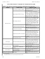
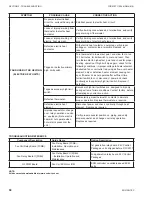
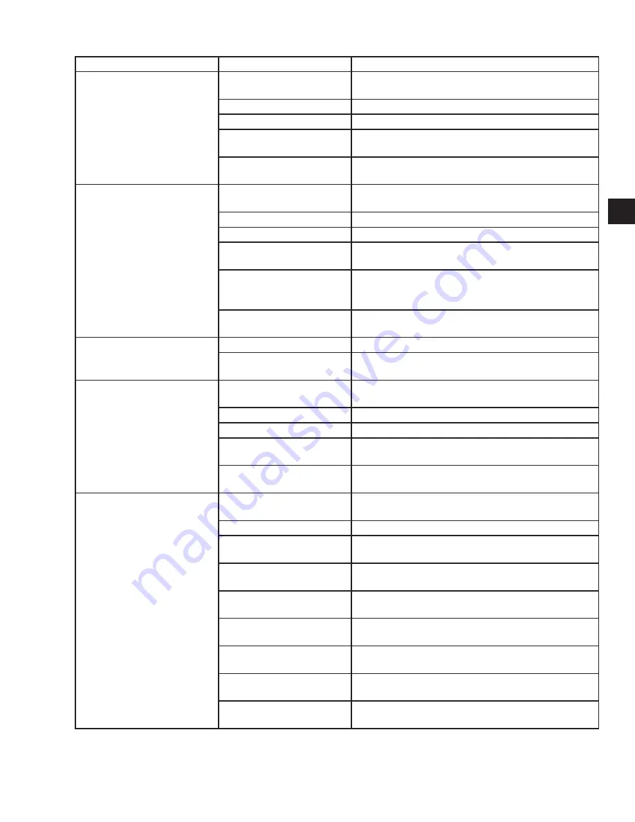
SYMPTOM
POSSIBLE CAUSE
CORRECTIVE ACTION
FAN MOTOR HUMS AND/OR
GETS HOT, BUT RUNS AT
REDUCED SPEED OR
NOT AT ALL
Improper power applied to
unit.
Apply proper power to unit.
Defective motor capacitor.
Replace with known good capacitor.
Defective fan motor.
Replace defective motor.
Blower wheel jammed in
housing.
Reposition blower wheel for proper alignment in housing,
or replace if damaged.
Foreign object in blower
wheel.
Remove foreign object and replace blower wheel if
damaged.
FAN RUNS BUT VIBRATES
Blower wheel dirty.
Remove and clean blower wheel taking care not to
remove or reposition balance weights.
Blower wheel bent.
Replace blower wheel.
Blower wheel out of balance.
Replace blower wheel.
Foreign object in blower
wheel.
Remove foreign object and replace blower wheel if
damaged.
Loose motor mount screws.
Verify proper motor and blower wheel position and
tighten motor mount screws. Do not crush mounting
grommets.
Broken motor mount frame or
mounting screws.
Replace motor or mounting screws.
FAN RUNS BUT BLOWER
WHEEL RUBS HOUSING
Bent blower wheel.
Replace blower wheel.
Blower wheel not positioned
properly on motor shaft.
Check for damage to blower wheel. Reposition blower
wheel on motor shaft or replace as required.
FAN RUNS BUT AIR
DELIVERY IS LOW
Incorrect fan speed has been
selected.
Reselect proper fan speed as required.
Dirty air filter.
Replace air filter.
Dirty coil.
Clean coil.
Obstruction in ductwork.
Check for improperly positioned balancing or fire
dampers. Check for fallen duct liner. Repair as required.
Actual E.S.P. higher than
design.
Check installation for proper supply and/or return grilles,
and compliance with plans and specifications.
FAN RUNS BUT NO COOLING/
HEATING. (HYDRONIC UNITS)
No chilled/hot water flow in
system.
Establish chilled/hot water flow in system as required.
Unit isolation valves closed.
Open unit isolation valves.
Debris in water piping
blocking flow.
Locate and clear debris from water piping as required.
Plugged strainer on units so
equipped.
Clean or remove strainer screen as required.
Riser or main flushing loop
open.
Close flushing loop valve as required.
Loose or improper wiring from
thermostat to control valve.
Verify all wiring connections and terminations, and verify
proper wiring of thermostat.
Defective thermostat.
Momentarily jumper thermostat contacts to simulate
proper operation. Replace thermostat as required.
Defective control valve
actuator.
Manually place control valve in “open” position using
lever on actuator housing. Replace actuator as required.
Improper aquastat operation
on units so equipped.
Verify proper aquastat position and operation. Replace
as required.
Summary of Contents for VHA
Page 10: ...ENVIRO TEC 10 FORM ET115 24 NOM4 819 THIS PAGE INTENTIONALLY LEFT BLANK ...
Page 41: ...ENVIRO TEC 41 SECTION 2 START UP FORM ET115 24 NOM4 819 THIS PAGE INTENTIONALLY LEFT BLANK ...
Page 54: ...ENVIRO TEC 54 FORM ET115 24 NOM4 819 SECTION 6 Dimensional Data 74 80083 ...
Page 78: ...ENVIRO TEC 78 FORM ET115 24 NOM4 819 SECTION 6 Dimensional Data NOTES ...


