ENVIRO-TEC
75
SECTION 6 - DIMENSIONAL DATA
FORM ET115.24-NOM4 (819)
6
VERTICAL HI-RISE TANDEM UNITS
VHA/VHB INSTALLATION INSTRUCTIONS
Receipt & Initial Installation
General
This publication details the installation requirements
for the Enviro-Pac dual unit configuration of the Verti-
cal High Rise, VH, unit assembly. Use of this docu-
ment for systems or products not manufactured or sup-
plied by ENVIRO-TEC shall not be applicable.
All products covered by this manual have been test-
ed in accordance with UL1479 (2012) - Fire Tests
Of Through Penetration Fire Stop Assemblies. Spe-
cific information about the ENVIRO-PAC VHA/VHB
UL1479 (2012) listing may be viewed on the Warnock
Hersey Listed Product Directory at https://whdirectory.
intertek.com. Reference WH file number JCI/PF60-01.
Specific ETL listed model numbers may be found in
the current ETL Listed Mark Directory at http://www.
intertek.com/directories/.
For other VH product installation and operational in-
structions, refer to IOM-FCUVH.
The Installation Instructions found within this manual
have been specifically drawn and detailed to meet the
requirements of UL1479 (2012). Some jurisdictions
may have additional installation requirements above
and beyond those detailed in this document; consult
with the authority having jurisdiction for specific ad-
ditional requirements. In all cases, the instructions de-
tailed in this document must be followed to maintain
the UL 1479 (2012) fire rating.
Installation
1.
In order to achieve the 1 hour fire rating, ENVI
-
RO-PAC unit assembly must be installed into a
minimum 1-hour fire rated wall assembly of gyp
-
sum and steel stud, gypsum and wood stud, con-
crete, or masonry construction with a minimum
overall thickness of 4-3/4”. The wall assembly
shall extend into the unit spacer plate. When ap-
plicable, attach studs of the wall to the unit spacer
plate with sheet metal screws spaced nominally
12” O.C. When built of gypsum construction, the
following minimum requirements must be met.
a. Studs – Wood or steel studs nominal 3-1/2”
thick, spaced maximum 24” O.C.
b. Gypsum Board – Minimum 5/8“ Type X
Gypsum board with a minimum of one layer.
Gypsum board must be installed on each side
of the wall assembly.
2. Place unit assembly in its desired location. Check
riser number, floor number, room number, and
unit tag number against the tag label on the unit,
making sure that the unit assembly is installed
with the space between the two units centered in
the wall between each room.
3.
Anchor unit assembly to floor through unit bot
-
tom. Due to floor leveling, some shimming may
be necessary so unit is plumb and square to floor/
ceiling.
4.
Install floor stud reception channels up to unit
sides at the connector plate.
5. Install ceiling stud reception channel over the unit
assembly, leaving space for riser penetration.
6. Install the wall studs into the recess in the unit
assembly using #6 x ½ drywall screws spaced as
necessary.
Avoid placing screws where they may pen-
etrate the risers, coil, piping, or electrical
system.
7.
Install balance of the studs into ceiling/floor re
-
ception channels at a spacing to meet project
specifications and local, state, or national codes.
In no cases should stud spacing be greater than
24” O.C.
8. Install studs from top of unit to ceiling. Locates
studs at each unit corner.
9. Make necessary electrical and plumbing connec-
tions to unit.
10.
Two installation configurations may be used for
the ENVIRO-PAC units. The following details
standard installation per
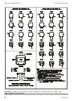
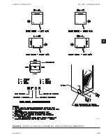
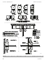
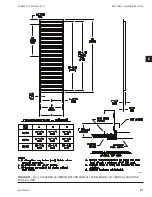
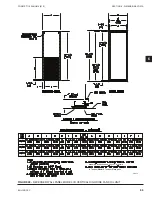
Figure 53 on page 76
.
a. Install minimum 5/8” Type X gypsum board
to all exposed sides of the unit exterior, in-
cluding top and front. Gypsum panels may
be applied directly to unit casing or may be
furred out for plumbness. Any supply air,
outside air, or thermostat openings shall be
let-in as necessary.
Summary of Contents for VHA
Page 10: ...ENVIRO TEC 10 FORM ET115 24 NOM4 819 THIS PAGE INTENTIONALLY LEFT BLANK ...
Page 41: ...ENVIRO TEC 41 SECTION 2 START UP FORM ET115 24 NOM4 819 THIS PAGE INTENTIONALLY LEFT BLANK ...
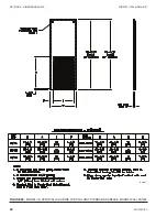
Page 54: ...ENVIRO TEC 54 FORM ET115 24 NOM4 819 SECTION 6 Dimensional Data 74 80083 ...
Page 78: ...ENVIRO TEC 78 FORM ET115 24 NOM4 819 SECTION 6 Dimensional Data NOTES ...


