ENVIRO-TEC
76
FORM ET115.24-NOM4 (819)
SECTION 6 - DIMENSIONAL DATA
b. The gypsum panel installed to the face of the
unit should be applied directly to the front
of the unit, unless a wall recessed return air
grille is used, in which case this panel will be
furred-out. Any supply air, return air, or ther-
mostat openings shall be let-in as necessary.
c. Attach gypsum board to unit with sheet met-
al screws spaced 8” O.C. around the perim-
eter and 12” O.C. in the field, ensuring that
screws are not located where they might pen-
etrate interior working of unit.
d. Gypsum board shall be tightly butted against
the wall assembly on all exposed sides, in-
cluding top of unit.
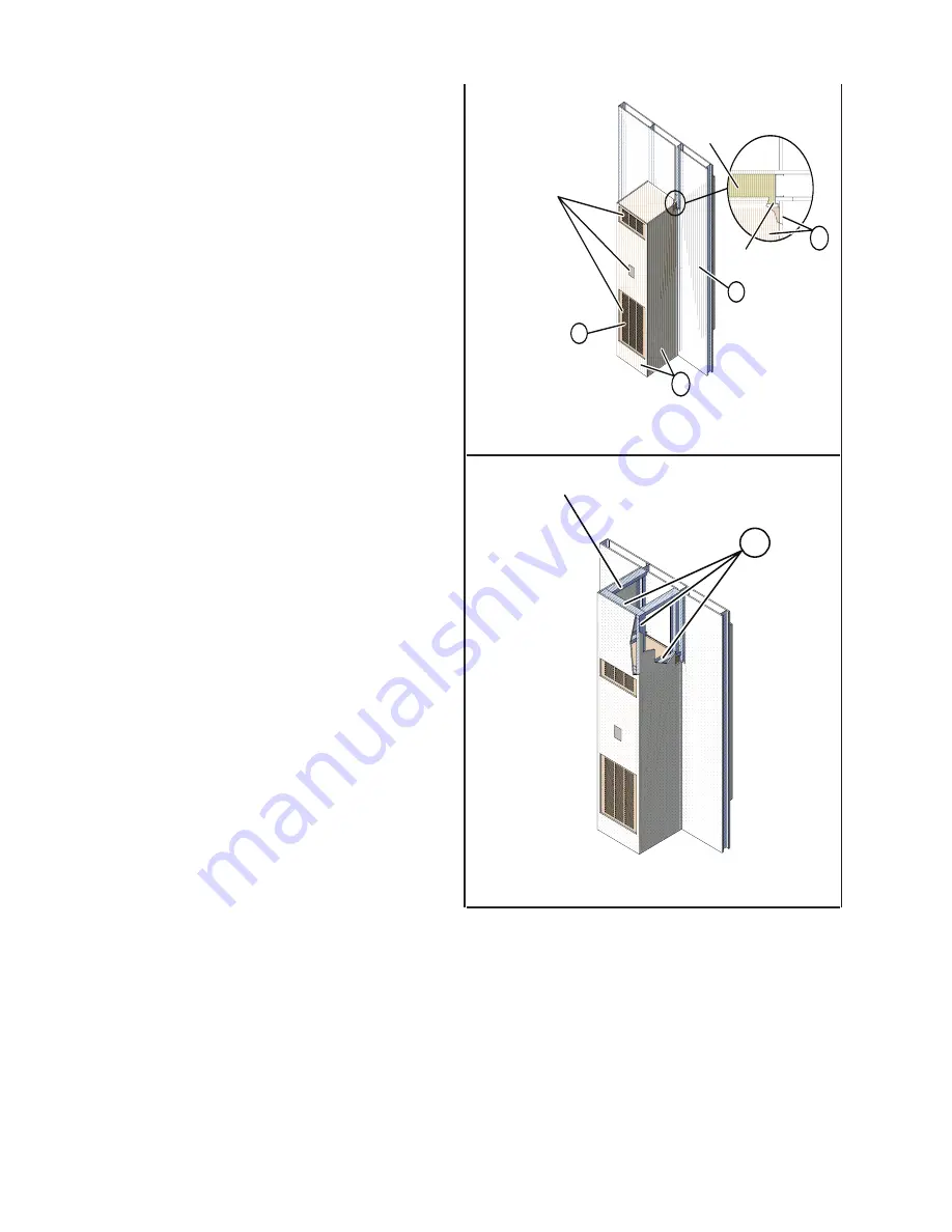
11. For alternate installation per
Figure 54 on page
76
, unit framing must be installed to top of unit.
a. Install minimum 25 GA, nominal 3-1/2”
wide, steel track to the top of the fan coil
unit, at top front and two top sides as shown
in
Figure 54 on page 76
.
b. Attach steel track using sheet metal screws
spaced 12” O.C.
c. Install identical steel track to the ceiling or
floor assembly using appropriate anchors.
Friction fit minimum 25 GA nominal 3-1/2”
steel studs into the top and bottom track and
secure with pan head screws.
d. Install one stud at each corner of the fan coil
unit.
e. Install gypsum board to the front and side of
the fan coil unit as described in Step 10.
f. Extend the gypsum board to the ceiling or
floor assembly, attaching to steel studs and
track with Type S screws spaced maximum
8” O.C.
12. Risers shown in the standard location. Risers may
be installed on the left or right side of Unit A. Wall
construction should remain the same, regardless
of riser location.
Gypsum may have cut out to
accomodate supply, return
and thermostat
1
1A
2
Factory Installed
Insulation
1A
Factory Installed
Gypsum
LD19316
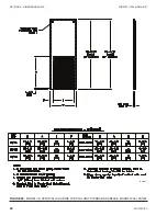
FIGURE 53 -
STANDARD INSTALLATION
Attached to pre-existing ceiling or floor assembly
1Bi
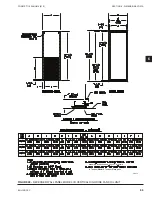
FIGURE 54 -
ALTERNATE INSTALLATION
LD19316
Summary of Contents for VHA
Page 10: ...ENVIRO TEC 10 FORM ET115 24 NOM4 819 THIS PAGE INTENTIONALLY LEFT BLANK ...
Page 41: ...ENVIRO TEC 41 SECTION 2 START UP FORM ET115 24 NOM4 819 THIS PAGE INTENTIONALLY LEFT BLANK ...
Page 54: ...ENVIRO TEC 54 FORM ET115 24 NOM4 819 SECTION 6 Dimensional Data 74 80083 ...
Page 78: ...ENVIRO TEC 78 FORM ET115 24 NOM4 819 SECTION 6 Dimensional Data NOTES ...

