background image

07-02185A EB280 

Legend Brands  

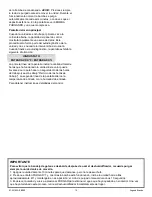
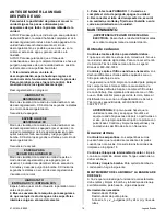
BEFORE MOVING UNIT AFTER USE 

To reduce the possibility of drips when moving the 
unit, follow these additional steps to ensure that all 
water is removed from the unit.  

NOTICE: To ensure all water is removed from the 
dehumidifier, the unit will complete the defrost cycle 
even if the unit is turned off. If the unit is unplugged 
during the defrost cycle, excessive water may 
accumulate in the unit and may drip out when you move 
the unit.  

NOTICE: To ensure the condensate tank empties 
completely while purging, make sure the unit is placed 
upright on a horizontal surface.  

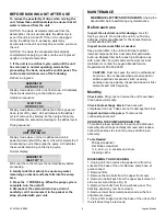
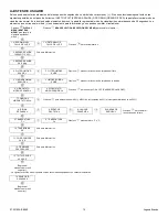
1. If the unit is in a defrost cycle, wait until the unit 
has returned to normal operating mode before 
proceeding. To check, review the control panel. The 
control panel will show one of the following: 

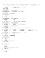
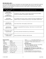
Defrost in progress: 

HUMIDISTAT 

DEFROST XX 

Display mode when unit is in defrost mode. XX indicates 
the seconds remaining on the defrost cycle. 

Shutdown sequence 

WAIT FOR  

DEFROST XX 

Display mode when unit in defrost and unit is powered 
down (shut off by user). Unit will complete the defrost 
cycle to remove any built-up ice then purge the pump. 
XX indicates the seconds remaining on the defrost cycle. 

Drying sequence 

WAIT FOR  

UNIT DRYING XX 

Display mode when unit not in defrost and unit is 
powered down (shut off by user). Unit will complete the 5 
minute drying cycle then purge the pump. XX indicates 
the seconds remaining on the drying cycle. 

Normal display: 

HUMIDISTAT 

INLET XX° C 

Wait until the control shows the normal display before 
proceeding.  

2. Gently rock the machine to ensure any water 
remaining on interior surfaces falls into the sump 
area.  

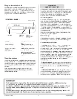
3. Press the 

 PURGE key. When the purge cycle is 

complete, turn the unit off.  

4. Disconnect the external drain hose, drain it 
carefully, coil it and secure it in the pocket or the 
strap provided with your unit.  

MAINTENANCE 

WARNING! ELECTRIC SHOCK HAZARD.

 Unplug the 

dehumidifier before performing any maintenance. 

Before each use 

Inspect the electrical cord for damage.

 Look for 

fraying, cuts, etc. Do not use the unit if you find any 
damage. Call Legend Brands for the nearest Service 
Center at 800-932-3030. 

Inspect and vacuum filter as needed.


Keep a clean filter in the unit at all times to protect 
internal components from dust and other particulate 
build-up. Replace filter before each job. Replace only 
with a new filter. For parts and service call your local 
distributor or contact the Legend Brands Service 
Department at 800-932-3030. 

CAUTION: 

Dust can cause the unit to overheat and 

shut down. Do not operate when excessive dust or 
airborne particles are present, such as during 
sanding or spray-painting. Inspect and clean air filter 
elements and coils frequently.


Monthly 

Check coils

. Dirty coils can cause the unit to overheat. 

Clean when visibly dirty.  

Check heat exchange block. 

Clean out with 

compressed air only. Take care not to damage the block.  

Inspect and clean the pump. 

To remove the 

condensate pump unit: 

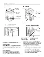
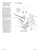
SERVICING THE PUMP AND DRAIN PAN 

To maintain proper operation, the pump and drain pan 
assembly should be periodically removed and cleaned. 
Follow these steps to clean the pump and drain pan 
assembly: 

Tools Needed  

Philips screwdriver 
Flat blade screwdriver 
⅜ in. and 

15

16

 in. sockets and driver 

Cleaning cloths  


DISASSEMBLY AND CLEANING 

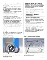
1. Unplug unit, then remove the power cord from the 
socket at the base of the unit. Remove pump hose at 
quick-connect. 
2. Remove filter. 
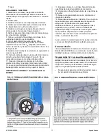
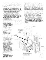
3. Remove the two bolts from the upper front cover.  
4. Remove one bolt each from the upper back corner of 
side covers A and B (see Fig. A)  
5. Remove four bolts from the lower back panel. The 
back/top panel may now be removed.  
6. Remove lower back metal panel (unscrew the five 
attachment screws).  
7. Place a firm support under the base of the unit so that 
the left wheel may be removed. 

Summary of Contents for EB280

Page 1: ...motor and wiring dry Do not attempt to repair the unit For Authorized Service Centers contact Legend Brands BEFORE YOU BEGIN Warranty If you determine service is required have your equipment model ser...

Page 2: ...Uncoil and straighten the entire drain hose Do not leave any of part of the hose coiled on the unit and do not place the end of the hose higher than 20 ft 6 m above the top of the unit Also check for...

Page 3: ...on or off When the machine is turned on the display normally reads PLEASE WAIT COMP DELAY and performs a numeral countdown for a maximum of 60 seconds to 0 This delay allows time for refrigerant pres...

Page 4: ...nd viewing system information Display setting changes and system information can be accessed by pressing DISPLAY MENU Each press of the key will display the next parameter see list below When you reac...

Page 5: ...30 For information only 3 GRAIN DPR XX GPP XX X g kg for 230V models 4 FILTER CLEANED XXX HRS 5 FILTER CLEANED 0 HRS Press to clear filter hours 5 COIL CLEANED XXX HRS 5 COIL CLEANED 0 HRS Press to cl...

Page 6: ...t in the pocket or the strap provided with your unit MAINTENANCE WARNING ELECTRIC SHOCK HAZARD Unplug the dehumidifier before performing any maintenance Before each use Inspect the electrical cord for...

Page 7: ...ATION AND STORAGE NOTICE Handle the unit carefully Do not drop throw or place the unit where it could fall Rough treatment can damage this equipment and may create a hazardous condition or void warran...

Page 8: ...for instructions To reassemble follow the above steps in reverse Be sure to reinstall heat exchange block in the original orientation When installing the rear cover carefully thread the pump hose thr...

Page 9: ...re to equalize None UNIT ON XXXX HRS INLET XXX F XX First line indicates total operating hours Second line Toggles between inlet temperature and inlet RH every 2 seconds None HUMIDISTAT INLET XXX F XX...

Page 10: ...NVALID MODEL SETTING Incorrect or unsupported DIP switch settings Contact service for correct DIP switch settings ER8 BUTTON STUCK ALL BUTTONS Key is stuck or has been held down too long Contact servi...

Page 11: ...siglas en ingl s No utilice el aparato en agua estancada Mantenga el motor y los cables secos ANTES DE COMENZAR La garant a Si considera que su producto necesita reparaci n tenga a mano el modelo del...

Page 12: ...e aire procesado deshumidificado Puede usarse con un conducto est ndar de 12 30 5 cm r gido o plano FIG A PARTE DELANTERA Armaz n rotomoldeado fuerte resistente a abolladuras y rayones y f cil de mant...

Page 13: ...atro teclas Presione la tecla PRENDIDO APAGADO para prender la unidad C mo usar el panel de control El panel de control tiene una pantalla y una placa sensible al tacto con cuatro teclas PRENDIDO APAG...

Page 14: ...a la cantidad total de horas que ha funcionado la unidad Este valor puede llevarse a cero para hacer un seguimiento de las horas de trabajo vea m s abajo Reinicio de las horas de trabajo La segunda l...

Page 15: ...115 30 S lo para informaci n 3 ENTRADA SALIDA XX X g kg 4 FILTRO LIMPIAR XXX HR 5 FILTRO LIMPIAR 0 HRS Presione para borrar las horas de limpieza del filtro 5 LIMPIAR BOBINA XXX HRS 5 LIMPIAR BOBINA...

Page 16: ...ores caiga en el rea del colector 3 Pulse la tecla de PURGADO Cuando se complete el ciclo de purgado apague la unidad 4 Desconectar el tubo de drenaje externo escurrir con cuidado enrollarla y fijarlo...

Page 17: ...evante la estructura de la bomba para sacarla de la bandeja pl stica de recolecci n y aparte la bomba LIMPIEZA DE LA BOMBA Y LA BANDEJA DE LA BOMBA 13 Enjuague o limpie con un trapo h medo todas las s...

Page 18: ...del serpent n condensador vertical hasta que est limpio No permita que la boquilla toque las aletas ya que podr a da arlas AVISO El limpiador de serpent n Legend Brands Coil Cleaner pieza n S402 de L...

Page 19: ...ci n Segunda l nea Alterna cada 2 segundos entre la temperatura de entrada y la humedad relativa de entrada Ninguna HIGROSTATO ENTRADA XXX C XX Primera l nea indica que la unidad est en modo de higros...

Page 20: ...st n instalados correctamente en el panel de control Si el error persiste comun quese al centro de servicio ER5 CONEXION SENSOR TABLERO Sensor de temperatura humedad relativa de entrada abierto faltan...

Page 21: ...100 F 1 38 C Construcci n Carcasa rotomoldeada Seguridad Certificaci n de ETL conforme a las normas CSA 22 2 n 92 Las especificaciones est n sujetas a cambios sin previo aviso Algunos valores pueden...

Page 22: ...teur Ne jamais sectionner la troisi me fiche Ne pas utiliser de rallonge L appareil doit fonctionner sur un circuit de 115V 60 Hz prot g par un disjoncteur de fuite la terre Ne pas mettre l appareil e...

Page 23: ...ge optimal contactez Legend Brands au 800 932 3030 IDENTIFICATION DES PI CES FIG A AVANT Panneau de commande R ceptacle moul pour rangement du cordon Entr e d air humide 2 c t s Sortie d air trait d s...

Page 24: ...nsion Mode d emploi du panneau de commande Le panneau de commande comprend un cran et un clavier tactile avec quatre touches MARCHE ARR T Appuyez sur la touche Marche Arr t pour mettre l appareil en m...

Page 25: ...FFICHAGE Appuyez pour s lectionner l article suivant du menu L article du menu apparaitra sur l affichage S LECTION DU MENU TOUCHE VERS LE HAUT Appuyez pour faire d filer ou s lectionner les valeurs a...

Page 26: ...ormation seulement 3 ENTRADA SALIDA XX X g kg 4 FILTRO LIMPIAR XXX HR 5 FILTRO LIMPIAR 0 HRS Appuyer sur pour effacer les heures du filtre 5 LIMPIAR BOBINA XXX HRS 5 LIMPIAR BOBINA 0 HRS Appuyer sur p...

Page 27: ...e l eau restant sur les surfaces int rieures s coule dans le puisard 3 Appuyez sur la touche PURGE Lorsque le cycle de purge est termin teignez l unit 4 D brancher le tuyau de vidange externe goutter...

Page 28: ...de fa on appropri e Remettez en place le roulement puis le clapet de non retour R assemblez les articles en suivant les tapes en sens inverse Le d shumidificateur est maintenant pr t l emploi Tous les...

Page 29: ...nt tre utilis sur le serpentin froid vaporateur horizontal Suivez les instructions fournies sur l tiquette du produit Veillez ne pas vaporiser ou taler le nettoyant pour serpentins sur des composants...

Page 30: ...fonctionnement Seconde ligne Alterne entre la temp rature d entr e et RH d entr e toutes les 2 secondes Aucune HIGROSTATO ENTRADA XXX C XX Premi re ligne indique que l unit est en mode hygrostat Secon...

Page 31: ...s capteurs de temp rature sont install s correctement sur le panneau de commande Si l erreur persiste contacter le fournisseur de services ER5 CONEXION SENSOR TABLERO Le capteur de la temp rature Rh d...

Page 32: ...38 C Construction Enveloppe rotomoul e S curit Certifi ETL pour CSA 22 2 no 92 La fiche technique peut tre modifi e sans avis pr alable Certaines valeurs peuvent tre approximatives Vitesse variable au...

Reviews: