24431
Rev. A
10/12
http: www.networketi.com
Environmental Technology, Inc.
66 of 94
Automatic Air Dehydrator
ADH
®
SIROCCO™
Instruction Manual
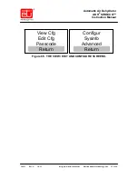
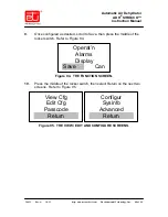
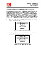
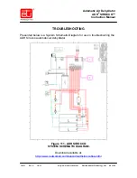
4.
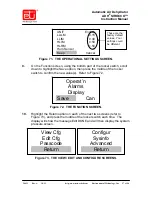
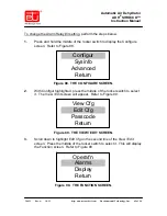
On the Function screen, scroll down to highlight Alarms, then press the
middle of the rocker switch. You will see the same information as on the
View Cfg screen, but this time, the line entries will be highlighted.
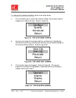
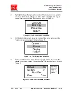
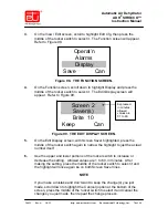
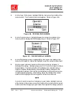
5.
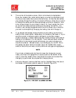
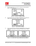
Scroll down to highlight Alrm3Sel, then press the middle of the rocker
switch to select it. Refer to Figure 91. To save display space, the alarm
conditions are referred to as explained in Figure 92.
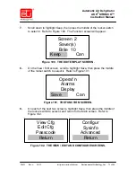
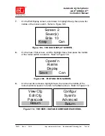
Figure 91. THE EDIT ALARMS SCREEN.
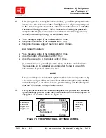
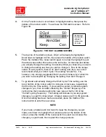
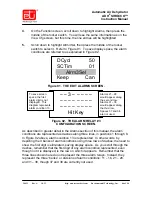
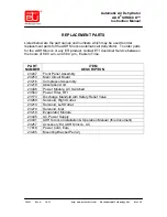
Figure 92. THE ALARM RELAY #3
CONFIGURATION SCREEN.
As described in greater detail in the Alarms section of this manual, the alarm
conditions are represented as dashes along three lines, in positions 1 through 8.
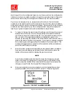
In Figure 92 above, alarm condition 13 is represented. In other words, by
depicting the 3 banks of alarm conditions using three rows of dashes, the need to
show the first digit is eliminated, saving display space. As you scroll through the
dashes, remember that the first digit of any alarm condition represented, even
though not it is displayed, is the row on which it appears. Remember that the
three lines shown here do not represent the three alarm relays. Instead, they
represent the three “banks” or divisions of alarm conditions: 11 – 18, 21 – 28,
and 31 – 38, though 37 and 38 are currently not used.
DCycl 50
SCTim 01
Alrm3Sel
Keep Can
– – 3 – – – – –
– – – – – – – –
– – – – – – – –
Hit Key
To save screen
space, the first
alarm digit is not
displayed. This
diagram represents
alarm condition 13.
Alarms 21 – 28
would appear along
the second row.
Alarms 31 – 36
would appear along
the third row.
Spaces 37 and 38
are not used.


