background image


24431 

Rev. A 

10/12 


http: www.networketi.com 

Environmental Technology, Inc. 

91 of 94 


Automatic Air Dehydrator 

ADH

®

 SIROCCO™ 

Instruction Manual 


5.


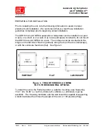
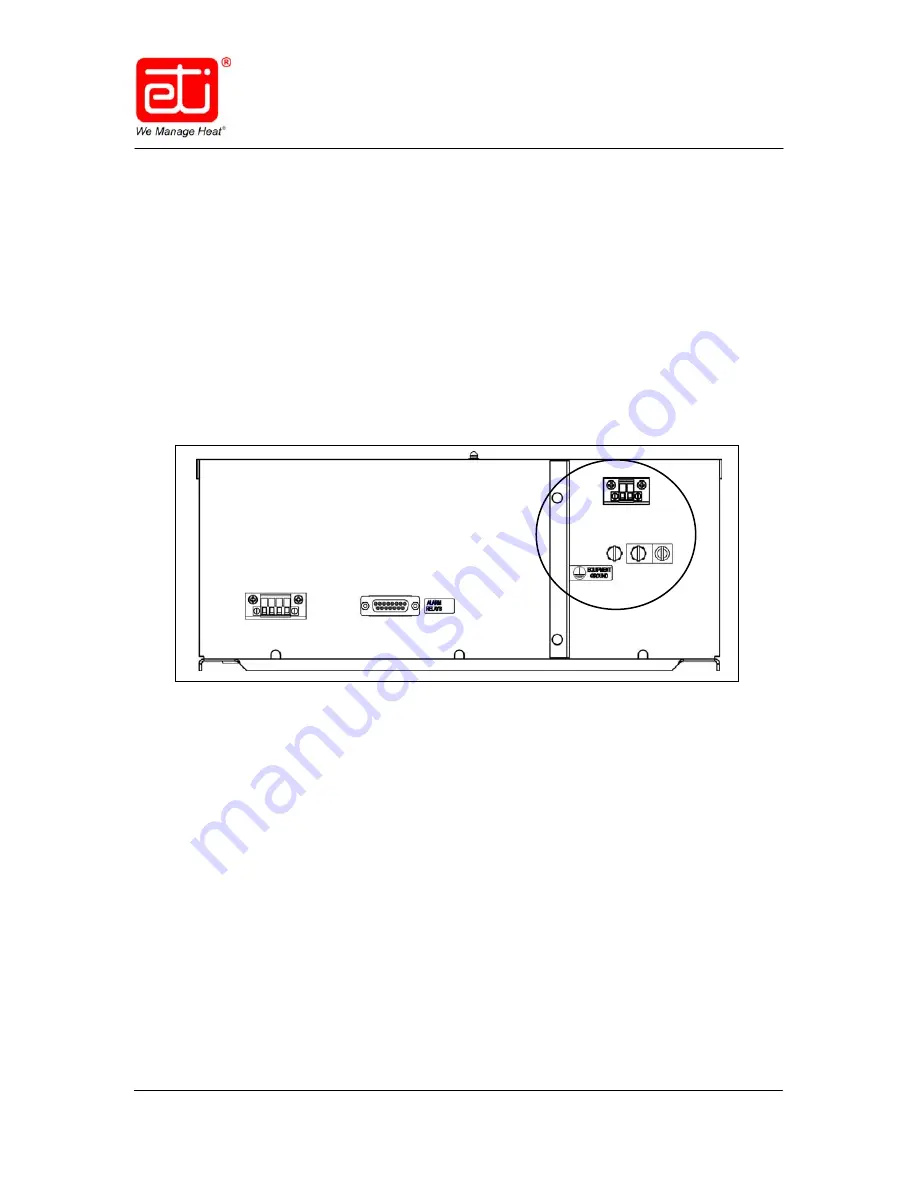
To install the power and ground wires, run the power and ground cables 
inside conduit through the 7/8” access hole in the bottom of the enclosure 
to the inside of the enclosure.  The 7/8” hole will accommodate 1/2” 
conduit.  Leave enough slack to extend the cables to their respective 
terminal lugs.  Remove enough of the insulation at the end of the wire or 
cable to be able to make the connection into their respective terminal lugs. 
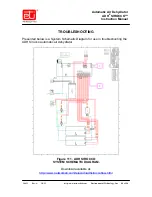
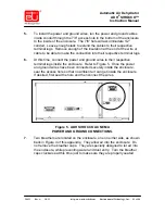
 

6.


At this time, connect the power and ground wires to their respective 
terminal lugs inside the enclosure.  Refer to Figure 5.  Once the power 
and ground wires have been connected securely inside the enclosure, 
seal the access hole so that no ambient air can get inside the enclosure.  
If desired, first seal the hole and then connect the wires. 


Figure 5.  ADH SIROCCO AC NEMA 

POWER AND GROUND CONNECTIONS. 
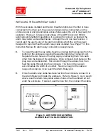
 

7.


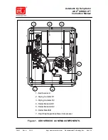
Two breathers are located on the enclosure, one on either side, as shown 
back in Figure 4 of this appendix.  They allow air into the enclosure.  Do 
not remove the breather caps.  They are specially designed to let air into 
the enclosure, while preventing water and dust entry.  Turn the breather 
caps clockwise at this time just to make sure they are properly seated. 


Summary of Contents for ADH Sirocco

Page 1: ...hnology Inc 1 of 94 Automatic Air Dehydrator ADH SIROCCO Instruction Manual Automatic Air Dehydrator ADH Sirocco Part Number 24434 Instruction Manual Environmental Technology Inc 1850 North Sheridan S...

Page 2: ...pumps inside the ADH Sirocco automatic air dehydrator is capable of generating as much as 24 psig 1 655mbar Other attached dry air sources may be capable of generating even higher pressures Proper saf...

Page 3: ...uring the Optional Humidity External Sensor Setting 39 To configure the optional external humidity sensor 39 Viewing the Current Settings 44 To view the current operational settings without changing t...

Page 4: ...Environmental Technology Inc Customer Service is available between 8 00 a m and 5 00 p m Eastern Time In the event of shipping damage keep the packing materials for inspection by the carrier RETURNS A...

Page 5: ...Mounting Screw 8 32 8 10641 8 Split Washer Table 1 PACKING LIST FOR THE ADH SIROCCO DATA LOG To get the best service from and gain the greatest understanding of your system it is recommended to keep...

Page 6: ...e for the dehydrator This is the pressure setting which the unit will target during compressor operation The actual turn off pressure is adjusted in the software every pressurization cycle after deter...

Page 7: ...indicated Note that the Low Pressure Alarm Level setting must be set lower than the Low Limit Target Pressure setting and that the factory default setting is 0 15 psig 10mbar A Low Pressure Alarm occ...

Page 8: ...d to basic mechanical features such as air drying and pressurization Product features include Similar specifications to earlier ADH dehydrator models Two air drying canisters with automatic desiccant...

Page 9: ...m Environmental Technology Inc 9 of 94 Automatic Air Dehydrator ADH SIROCCO Instruction Manual ADH SIROCCO COMPONENTS An assembly drawing of ADH Sirocco Automatic Air Dehydrator is presented in Figure...

Page 10: ...ining a 5 or lower duty cycle ADH Sirocco AUTOMATIC AIR DEHYDRATOR ORIGINAL COMPONENT AND REPLACEMENT PART RELIABILITY LIST Item Number Part Description Replacement Part Number MTBF hours Storage C 1...

Page 11: ...le and related components used in earth station and terrestrial UHF and microwave communication systems dry PRINCIPAL CONSIDERATIONS The ADH Sirocco automatic air dehydrator works best supplying dry a...

Page 12: ...ng canister is brought into service and the used canister is regenerated The drying canister being regenerated is heated internally until a temperature is attained which will convert all absorbed wate...

Page 13: ...2 Figure 2 THE ADH SIROCCO The ADH Sirocco automatic air dehydrator includes three alarm relays which communicate alarm conditions These are configured at the factory for Summary Alarm Low Pressure Al...

Page 14: ...regeneration even though moisture has not reached levels that would be considered wet This ensures that the drying agent is periodically regenerated even in low dew point conditions to extend the lif...

Page 15: ...ing Part Number 23428 connects a 1 8 NPT to a 3 8 barbed fitting It is recommended to use Part Number 23428 with the 3 8 barbed fitting on runs of longer than one hundred 100 feet or about 30 meters F...

Page 16: ...round protection as well but this provides additional ground protection for increased safety Figure 5 ADH SIROCCO REAR PANEL DETAIL 6 For optional remote communication of the alarm conditions connect...

Page 17: ...gure the dehydrator for wall mount installation remove the front panel and the portion of the vented cover with the ETI logo then re install each where the other had been Reinstall the front panel so...

Page 18: ...not supplied or on support channels mounted on the inside of the relay rack Because the dehydrator seldom requires operator attention a location in the lower portion or extreme upper portion of the r...

Page 19: ...ttp www networketi com Environmental Technology Inc 19 of 94 Automatic Air Dehydrator ADH SIROCCO Instruction Manual Figure 9 ADH SIROCCO RACK MOUNT HOLE DIMENSIONS Figure 10 ADH SIROCCO SLIDE RAIL MO...

Page 20: ...ydrator ADH SIROCCO Instruction Manual Figure 11 MOUNTING BRACKETS IN FLUSH MOUNT POSITION Figure 12 MOUNTING BRACKETS IN 2 INCH DEPTH POSITION Install mounting brackets as shown for flush mount insta...

Page 21: ...tor ADH SIROCCO Instruction Manual Figure 13 MOUNTING BRACKETS IN 6 INCH DEPTH POSITION Figure 14 MOUNTING BRACKETS IN 8 INCH DEPTH POSITION Install mounting brackets as shown for 6 inch depth mount i...

Page 22: ...approximately 17 high by 19 wide and will project almost 6 out from the wall Refer to Figure 15 Plan your installation so that the ADH Sirocco will not interfere with normal traffic patterns at your s...

Page 23: ...mounting brackets will accommodate fasteners up to 1 4 6mm in diameter The choice of anchors and companion hardware should be appropriate for the mounting surface At least four anchors minimum one per...

Page 24: ...r ADH SIROCCO Instruction Manual Figure 17 WALL MOUNT POINT DIMENSIONS POWER CONNECTIONS The ADH Sirocco uses a standard NEMA 5 15P to IEC 320 C13 power cord included Part Number 17618 If the power co...

Page 25: ...ll give you the opportunity to cancel any incorrect or undesired changes you might make by mistake before those changes can take effect or have any adverse or undesired impact on system operation 1 A...

Page 26: ...a Can or Cancel option Refer to Figure 20 To cancel or discard a change scroll down to highlight Can at the bottom of the screen then select it by pressing the middle of the rocker switch The message...

Page 27: ...he screens then press the middle of the rocker switch Refer to Figure 21 Repeat as necessary highlighting Return then pressing the middle of the rocker switch until the system pressure Main screen app...

Page 28: ...you can go back into the Edit Cfg mode to change whichever setting s you desire When finished write down all of the current configuration settings in case they ever need to be restored 6 It is recomme...

Page 29: ...l 50 SCTim 01 Alrm3Sel Keep Can Unit English LALR 0 15P LLIM 0 30P HLIM 0 50P HLRM 1 50P Hum Sensor Y Keep Cancel To view the current settings only without changing them select the View Cfg option To...

Page 30: ...ading PSI or mbar the second line in larger type is the current system pressure reading itself and the third line displays any current alarm conditions Should there be more than one current alarm cond...

Page 31: ...Being regenerated Figure 23 shows a sample Status screen with no current alarm conditions Figure 23 A TYPICAL CANISTER STATUS SCREEN The Cycle Information screen presents dehydrator cycling informati...

Page 32: ...nctions are available which are used only for troubleshooting or diagnostic purposes These functions are passcode protected and are not part of normal operations They are used only when working with T...

Page 33: ...iew or change any of the actual system settings To view the Sysinfo screen perform the steps below 1 With power running to the unit press and hold the middle of the rocker switch until you see the Con...

Page 34: ...well as the revision level of the firmware inside your unit There is nothing on this screen that can be changed it is just for reference should the information be needed When finished viewing the info...

Page 35: ...re and the system air pressure units of measure will be changed at the same time To toggle from either unit of measure to the other perform the steps below 1 With power running to the unit press and h...

Page 36: ...hlighted on the View Edit screen press the middle of the rocker switch to select it The Function screen will display Refer to Figure 32 Figure 32 THE FUNCTION SCREEN 5 On the Function screen Operat n...

Page 37: ...p or the bottom of the rocker switch then press the middle of the rocker switch to enter the change The entire line will again be highlighted 8 Scroll down and highlight the Keep option at the bottom...

Page 38: ...each of the next two screens scroll down to highlight Return then press the middle of the rocker switch each time Refer to Figure 36 The message Edit DONE will appear and the display will return to th...

Page 39: ...umidity sensor before operating the system To verify the proper setting has been made for the humidity sensor perform the steps below Note that this can be verified by using the View mode also but we...

Page 40: ...W EDIT SCREEN with View Cfg highlighted 3 On the View Edit screen View Cfg should already be highlighted Press the bottom of the rocker switch to highlight Edit Cfg then press the middle of the rocker...

Page 41: ...ed by pressing the middle of the rocker switch the highlight will narrow to just the one letter at the end of that line 7 If the character at the end of that line is a Y for Yes the dehydrator is curr...

Page 42: ...at the bottom Refer to Figure 44 Press the middle of the rocker switch to select it Figure 44 THE FUNCTION SCREEN 10 On each of the next two screens scroll down to highlight Return then press the mid...

Page 43: ...s been built into the system software from the time the Y configuration is made until the time Alarm 17 is indicated in the display window HUMSENSR This delay allows for the installation of the humidi...

Page 44: ...elow 1 From the Main screen press and hold the middle of the rocker switch until the display changes This will display the Configure screen Refer to Figure 46 Figure 46 THE CONFIGURE SCREEN 2 The firs...

Page 45: ...tice that on the View Operational Settings screen there are no highlighted lines This is because this is not the screen used to change the operational settings but only to view them 6 While the operat...

Page 46: ...ion on the last line of the Function screen refer to Figure 50 as well as each of the next two screens refer to Figure 51 then press the middle of the rocker switch each time to return to the Main scr...

Page 47: ...reen Refer to Figure 52 Figure 52 THE CONFIGURE SCREEN 2 With Configur highlighted on the Configure screen press the middle of the rocker switch to select it The View Edit screen will be displayed Ref...

Page 48: ...Alarms highlighted on the Function screen press the middle of the rocker switch to select it The View Alarm Settings screen will be displayed Refer to Figure 56 Figure 56 THE VIEW ALARMS SCREEN 6 On...

Page 49: ...THE VIEW ALARM RELAY 3 SCREEN 8 Press the middle of the rocker switch to begin returning to the Main screen On each of the next three screens refer to Figures 58 and 59 scroll down to highlight Return...

Page 50: ...creen Refer to Figure 60 Figure 60 THE CONFIGURE SCREEN 2 With Configur highlighted on the Configure screen press the middle of the rocker switch to select it The View Edit screen will be displayed Re...

Page 51: ...rrent display settings Refer to Figure 64 Figure 64 THE VIEW DISPLAY SCREEN 6 As prompted at the bottom of the display press the middle of the rocker switch to back out of this function and begin retu...

Page 52: ...ww networketi com Environmental Technology Inc 52 of 94 Automatic Air Dehydrator ADH SIROCCO Instruction Manual Figure 66 THE VIEW EDIT AND CONFIGURE SCREENS View Cfg Edit Cfg Passcode Return Configur...

Page 53: ...must be at least 0 01 PSI higher than the High Pressure Limit Additionally there are other requirements for each of the settings that an operator must know The Low Pressure Alarm must be set to at le...

Page 54: ...ONFIGURE SCREEN 2 Use the lower edge of the rocker switch to scroll down to highlight the second line on the View Edit Screen Edit Cfg then press the middle of the rocker switch to select it Refer to...

Page 55: ...er switch 3 times press the middle of the rocker switch 1 time press the lower edge of the rocker switch 3 times As described above you will press the rocker switch a total of 14 times The passcode wi...

Page 56: ...rease or decrease any value automatically you might notice that the numbers stop advancing whether up or down as you near the allowable upper or lower range This is done deliberately so that the setti...

Page 57: ...to Figure 72 Figure 72 THE FUNCTION SCREEN 10 Highlight the Return option on each of the next two screens refer to Figure 73 and press the middle of the rocker switch each time The display will show t...

Page 58: ...gured to signal a change in the system about which the operator should know before a larger problem develops If for instance your system normally runs at a 5 Duty Cycle DCycl on the screen which is to...

Page 59: ...o Figure 75 Figure 75 THE VIEW EDIT SCREEN 3 With Edit Cfg highlighted press the middle of the rocker switch and the Function screen will appear Refer to Figure 76 Figure 76 THE FUNCTION SCREEN 4 On t...

Page 60: ...op or bottom of the rocker switch respectively to increase or decrease it If you want the system to indicate system changes to you before a larger problem develops consider decreasing the 50 percent D...

Page 61: ...ss the middle of the rocker switch to select it Refer to Figure 79 Figure 79 THE FUNCTION SCREEN 9 On the next two screens scroll to highlight Return then press the middle of the rocker switch to work...

Page 62: ...igure 81 Figure 81 THE CONFIGURATION SCREEN 2 Highlight Configur then press the middle of the rocker switch to select it The View Edit screen will appear Refer to Figure 82 Scroll down to highlight Ed...

Page 63: ...s however very strongly suggested that if you don t know why or what it is you wish to accomplish by changing the setting then don t change it 6 To go ahead and actually change the Short Cycle Time se...

Page 64: ...tion screen scroll down to highlight Save then press the middle of the rocker switch to select it Refer to Figure 86 Figure 86 THE FUNCTION SCREEN 9 On the next two screens scroll down to highlight Re...

Page 65: ...88 THE CONFIGURE SCREEN 2 With Configur highlighted press the middle of the rocker switch to select it The View Edit screen will appear Refer to Figure 89 Figure 89 THE VIEW EDIT SCREEN 3 Scroll down...

Page 66: ...epresented as dashes along three lines in positions 1 through 8 In Figure 92 above alarm condition 13 is represented In other words by depicting the 3 banks of alarm conditions using three rows of das...

Page 67: ...n alarm relay 3 You can select as many as you like As each of the appropriate dashes is highlighted select it as desired by pressing the middle of the rocker switch and it will turn from a dash to the...

Page 68: ...ired scroll to Save then press the middle of the rocker switch Refer to Figure 94 Figure 94 THE FUNCTION SCREEN 10 Press the middle of the rocker switch then select Return on the next two screens Refe...

Page 69: ...and the second is the display brightness level To change the screen saver time setting perform the steps below 1 Press and hold the middle of the rocker switch to display the Configure screen Refer to...

Page 70: ...aver highlighted press the middle of the rocker switch again to narrow the highlight to just the actual number itself 6 Use the upper and lower portions of the rocker switch to increase or decrease th...

Page 71: ...SCREEN 8 On the View Edit screen scroll to highlight Save then press the middle of the rocker switch to select it Refer to Figure 101 Figure 101 THE FUNCTION SCREEN 9 On each of the next two screens...

Page 72: ...y logo If there is a current alarm condition however you will see a screen saver with a warning symbol to indicate that condition Refer to Figure 103 Press the middle of the rocker switch to display t...

Page 73: ...etting be used As more light will likely be required while actively configuring the unit consider using a brighter setting while actually making or changing the system settings then turning the bright...

Page 74: ...Use the upper and lower portions of the rocker switch to increase or decrease the setting Allowed values are 2 to 15 with the higher numbers being brighter To prolong the life of the display unit con...

Page 75: ...EEN 8 On the View Edit screen scroll to highlight Save then press the middle of the rocker switch to select it Refer to Figure 109 Figure 109 THE FUNCTION SCREEN 9 On the next two screens highlight Sa...

Page 76: ...Cycle 16 LEAKY Leaky no progress made toward pressurization 17 HUMSENSR Humidity Sensor missing when it should be present or present when it should not be 18 STOPPED Derived other alarm s causes dehy...

Page 77: ...acting meaning that the state they take when there is an alarm is the same state they take when there is no power Alarm relay 1 is a Summary alarm meaning that any of the 22 alarm conditions will cau...

Page 78: ...both located on the front panel of the unit The Power indicator lights up whenever power is running to the unit The Alarm indicator functions as a summary alarm and lights up to indicate the presence...

Page 79: ...re attempting to service or repair an ADH Sirocco unit WARNING Servicing should be performed by qualified personnel ADH Sirocco dehydrators contain lethal voltages Assume that all circuits are live At...

Page 80: ...Dehydrator ADH SIROCCO Instruction Manual TROUBLESHOOTING Presented below is a System Schematic Diagram for use in troubleshooting the ADH Sirocco automatic air dehydrator Figure 111 ADH SIROCCO SYSTE...

Page 81: ...rvice between the hours of 8 00 a m and 5 00 p m Eastern Time PART NUMBER ITEM DESCRIPTION 23247 Front Panel Assembly 23253 Main Circuit Board 23216 Compressor Assembly 23218 Absorption Unit 23446 Pow...

Page 82: ...4 432mm 330mm 133mm Weight 16 lbs 7 26 kg Mounting Dual post rack flush mounted Single post rack center mounted Wall mounted POWER Supply 100 240 VAC 50 60 Hz Maximum Current 0 9 Amps at 100 V Power...

Page 83: ...30 psig 21 mbar Low Pressure Alarm Level User Configurable Default 0 15 psig 10 mbar High Pressure Alarm Level User Configurable Default 1 5 psig 103 5 mbar Alarm Relays Contact Type Form C SPDT reve...

Page 84: ...4 Automatic Air Dehydrator ADH SIROCCO Instruction Manual ORDERING INFORMATION Order Number Description 24434 ADH Sirocco Automatic Air Dehydrator 24431 ADH Sirocco Instruction and Operation Manual th...

Page 85: ...rd and AC NEMA versions are the same 100 to 240VAC or 20 to 75VDC 50 60Hz and 1 5 Amps at 100V Each voltage range is auto sensing and requires no special configuration The temperature control system i...

Page 86: ...86 of 94 Automatic Air Dehydrator ADH SIROCCO Instruction Manual 1 Inlet Solenoid 2 Drying Canister 1 3 Drying Canister 2 4 Outlet Solenoid 1 5 Outlet Solenoid 2 6 Outlet Manifold 7 Dual Diaphragm Bru...

Page 87: ...24431 Rev A 10 12 http www networketi com Environmental Technology Inc 87 of 94 Automatic Air Dehydrator ADH SIROCCO Instruction Manual Figure 2 ADH SIROCCO AC NEMA ENCLOSURE DIMENSIONS...

Page 88: ...on a wall Due to size and space constraints do not mount the ADH Sirocco AC NEMA on a rack The enclosure can be oriented with the hinges on the left side of the box portrait along the top of the box...

Page 89: ...the bottom of the enclosure for a conduit connection for the electrical wiring The customer is responsible for installing the unit in a secure Restricted Access Location accessible only by personnel...

Page 90: ...ler do not force it into place as doing so might strip the threads If the muffler does not screw onto the drain port fitting easily carefully unscrew it reseat it try screwing it in again If using a h...

Page 91: ...lugs 6 At this time connect the power and ground wires to their respective terminal lugs inside the enclosure Refer to Figure 5 Once the power and ground wires have been connected securely inside the...

Page 92: ...ction Manual for alarm relay connector pin assignments 8 To install the alarm relay cable begin by unscrewing the plug cap from the bottom of the enclosure covering the weather tight gray connector po...

Page 93: ...lly once installation is complete turn the facility circuit breaker back on and verify that the installation was successful The unit will make a vibrating sound when the pump is operating CONFIGURING...

Page 94: ...plied warranties of merchantability or fitness for any particular purpose Environmental Technology Inc reserves the right to revise this publication and to make changes and improvements to the product...

Reviews: