Copyright EnvironmentalLights.com
All Rights Reserved 10/1/18
6
8-bit and 16-bit Modes:
These decoders are capable of operating in standard 8-bit DMX mode or in high-resolution 16-
bit mode. The decoder should be left in 8-bit mode unless the DMX controller is configured
specifically for 16-bit resolution. 16-bit mode assigns two DMX input channels for each of the
four outputs. The first channel operates like a normal DMX channel, 256 steps between off and
maximum brightness. The second channel provides 256 micro-steps between each step of the
first channel. This allows for over 65,536 adjustment steps, but requires twice as many DMX
channels.
Always turn off power to the decoder before changing between 8- and 16-bit modes.
DMX Address:
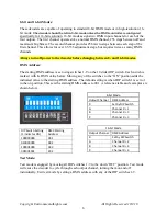
The starting DMX address is set using switches 1-9 on the 10 slider DIP switch. Each switch is
marked with its DMX value below. Moving any of the switches to the “ON” position adds the
indicated value to the starting DMX address. The default setting is when DIP switch 1 is set to 1
in the on position. This sets the starting DMX address to 001. A reference table and examples are
shown below.
Test Mode:
Test mode is engaged by moving all DIP switches 1-9 to the down “OFF” position. Test mode
will cause the decoder to cycle through each output channel, turning them on and off
individually. Exit test mode by setting a DMX address with any of the DIP switches 1-9.
8-bit Mode
Output Channel
DMX Address
R
Set by DIP Switch
G
Channel R + 1
B
Channel R + 2
X
Channel R + 3
16-bit Mode
Output Channel
DMX Address
R
Set by DIP Switch
G
Channel R + 2
B
Channel R + 4
X
Channel R + 6
DIP Switch Setting
(1 indicates ON)
DMX Starting
Address
100000000
001
010000000
002
100001000
033
001001001
292

