background image

Copyright EnvironmentalLights.com 


All Rights Reserved 10/1/18 

PWM Frequency: 


The output PWM frequency is set through this parameter, with “XX” being the frequency in 
kHz. The default value is “01”, corresponding to 1kHz. Options range from “00” = 500Hz to 
“30” = 30kHz. 

The output PWM frequency can be adjusted to avoid flicker in different settings. It can be left at 
1kHz for most applications. For on-camera use, settings around 5kHz are typically sufficient to 
eliminate flicker. Very high frequency settings (over 10kHz) should be used only if necessary. 
Very high frequency signals can be distorted by long cable runs and/or environments will a lot of 
electrical signals. 


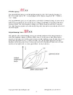
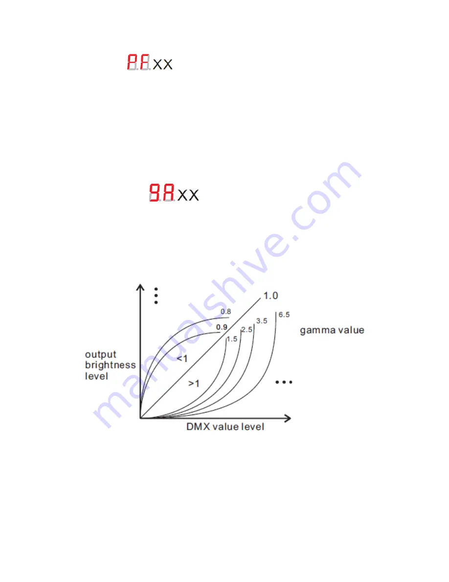
Output Dimming Curve: 


The “gamma” value of the dimming curve is set with this parameter. This changes the rate at 
which the brightness changes at different DMX values. It can be used to make dimming less 
sensitive at the high or low end for greater precision in that brightness range. Default value is 1.5 
and can be adjusted from 0.1-9.9. Values less than 1 give greater dimming precision at high 
brightness and values greater than 1 increase precision at low brightness. Human vision is more 
sensitive at low light levels, so values greater than 1 are most common. 


Summary of Contents for DMX-5-8A

Page 1: ...uency bit rate and dimming curve DMX connection options include 5 pin XLR RJ45 and terminal blocks for input and output Features Digital readout legibly displays the DMX address which is useful in dim...

Page 2: ...LED voltage and that the power supply is unplugged 2 Connect the LEDs and power supply to the DMX 5 8A using the screw terminals Power supply positive and ground should be connected to V and GND termi...

Page 3: ...s the utilize all five output channels using fewer DMX channels Based on the number of independent channels needed the outputs will be mapped as follows Note this mapping is for DMX starting address 0...

Page 4: ...hould be used only if necessary Very high frequency signals can be distorted by long cable runs and or environments will a lot of electrical signals Output Dimming Curve The gamma value of the dimming...

Page 5: ...setting is indicated above each table CH03 dP1 1 dP2 1 dP4 3 dP5 3 001 Dimming output 1 Dimming output 1 Dimming output 1 Dimming output 1 002 Dimming output 2 Micro dimming output 1 Dimming output 2...

Page 6: ...3 Strobe 007 Dimming output 4 5 008 Micro dimming output 4 5 Decoding Mode DMX Channel CH05 dP1 1 dP2 1 dP6 5 dP7 5 001 Dimming output 1 Dimming output 1 Dimming output 1 Dimming output 1 002 Dimming...

Page 7: ...many LEDs for your power supply and you might need a bigger supply or shorter runs Use a bus structure as described in rgb_manual pdf Call if you need assistance with larger projects 4 Connect everyth...

Reviews: