background image

VCC/A18-1

VCC/A15-1

VCC/A18-2

VCC/A15-2

/CS0
/CS1

/CS3

/IOCS0 PROT

PA0

PA1

PA2

PA3

PA4

PA5

PA6

PA7

PB0

PB1

PB2

PB3

PB4

PB5

PB6

PB7

PC0
PC1

PC2

PC3

PC4

PC5

PC6

PC7

PD0

PD1

PD2

PD3

PD3

PD4

PD5

PD6

PD7

BD0
BD0
BD1
BD1

BD2
BD2

BD3
BD3
BD4

BD5

BD6
BD6

BD7
BD7

BA0

BA0

BA1

BA1

BA2

BA3

BA4

BA5

BA6

BA7
BA8

BA9

BA10

BA11
BA12

BA13

BA14

BA15

/IOCS3
/IOCS3
/IOCS4

/IOCS5
/IOCS5

/IOCS6
/IOCS6

/BM1
/BM1
/BIORQ
/BIORQ
/BRD
/BRD

/INT0
/INT0

/BMERQ

/IOCS7

Inutilise
Inutilise
Inutilise
Inutilise
Inutilise
Inutilise
Inutilise

PE7

PE6

PE5

PE4

PE3

PE2

PE1

PE0

BD0

BD1

BD2

BD3

BD4

BD5

BD6

BD7

BA0
BA1
BA2
BA3
BA4
BA5
BA6
BA7

BA8
BA9
BA10
BA11
BA12
BA13
BA14
BA15

/BWR
/BRD

/BM1

/BIORQ
/BMERQ

/BWR

/BRESET

/BNMI

/BNMI

/WR PROT

/CS2 PROT
/CS3 PROT

/IOCS0
/IOCS1
/IOCS2
/IOCS7

/IOCS4

/IOCS5

/WR
/IORQ

/EN

/RESET

IEO
IEO

/M1

/IORQ

IEO

IEO

/IOCS0

/IOCS3
/IOCS4
/IOCS5
/IOCS6
/IOCS7
/EN

/MERQ

/RESET

/INT1

/RD
/WR

/M1
/IORQ
/RD

/INT2

CLK

CLK
/RESET
/WR
/RD
/IORQ
/MERQ
/M1
/INT0
/NMI

CLK

BCLK

/RESET

/MERQ

/IORQ

/M1

/RD

/WR

/NMI

BCLK

BCLK

/BRESET
/BRESET

Reset

/IOCS4

/IORQ
/M1

/IOCS2A
/EN

/IOCS3
/IOCS6

/RD

/MERQ

/CS2

PE0

PE1

PE2

PE3

PE4

PE5

PE6

PE7

DIR

DIR

/IORQ
/M1

/IOCS1

/IOCS1
/WR

/IORQ
/M1

/WR

INTACK

/CS1
/CS1A

INTACK

/RESET

/RESET
/IOCS0

/INT1
/RD

/CS1A

/CS1

DIR

BD0
BD1
BD2
BD3
BD4
BD5
BD6
BD7

GND
GND

+5V
+5V

+15V
+15V
-15V
-15V

PE3

IEO

/BRESET

/BRD

/BWR

1

0

0

0

1

0

1

1

Interfaces

2xRS232

2XRS422

Mixte

A3

A4

/IOCS2A

/CS2

/CS3

INTACK

BA1

BA0

03/03/98

NON UTILISE

ENTREES/SORTIES

GESTION AFFICHAGE/CLAVIER

SORTIE BUS SERIE SYNCHRO

E-1

E-2

Integration RS3i + BUS SERIE S S2 = 24 br.

Remplacement de PT2-3-4 par un connecteur 3 broches

12/98

12-98

03/06/99

ISOLATED 232/422 TRANSMISSION

SYNCRHO SERIAL BUS OUTPUT

PRINTER LINK

INPUTS/OUTPUTS

Aucune/NONE

STATIC RAM

STATIC RAM

HORLOGE/CLOCK

Inutilise/Unused

KEYBOARD/DISPLAY MANAGMENT

F

Modif c.i + supprimer R30=10K + remplacement Z80 par Z8S

05/08/98

99-081

UNUSED

NOTE:MIR 9000 U2=X24C65P

Standard U2=X24C16P

R30 = non utilisé/not used

Test point

Test point

NON UTILISE

UNUSED

2003-188

NL

NL

NL

Conversion compatible "RoHS"EEE"

H

NL

24/11/06

I

Remplacement EEPROM AT24C16A-10PU-2V7 par M24C16WBN6P

15/01/08

NL

2006-131

2007-277

Remplacement quartz Q2 paur cause d'obsolescence

J

13/02/08

NL

2007-274

Mise à jour dossier technique

K

12/02/08

NL

2008-158

A0

A0

A0

A0

A1

A1

A1

A1

A2

A2

A2

A2

A3

A3

A3

A3

A4

A4

A4

A4

A5

A5

A5

A5

D0

A6

D0

A6

D0

A6

D0

A6

D1

A7

D1

A7

D1

A7

D1

A7

D2

A8

D2

A8

D2

A8

D2

A8

D3

A9

D3

A9

D3

A9

D3

A9

D4

A10

D4

A10

D4

A10

D4

A10

D5

A11

D5

A11

D5

A11

D5

A11

D6

A12

D6

A12

D6

A12

D6

A12

D7

A13

D7

A13

D7

A13

D7

A13

TXS

A14

A14

A14

A14

A15

A15

CKS

A16

A16

A16

A16

A17

A17

A17

A17

RXS/CTS1-

A18

A18

RXS/CTS1-

TXS
CKS

A0
A1
A2
A3
A4
A5

A16

A0

A6

A17

A1

A7

A13

A3

A2

A8

A14

A3

A9

A19

A10

A18

A11

D0

A12

D1

A13

D2

A14

D3

A15

A15

A16

A12

A17
A18
A19

D0
D1
D2
D3
D4
D5
D6
D7

PF0

PF1

PF2

BA2

A8
A7
A6
A5
A4
A3

D7
D6
D5

D0

D4

D1

D3

D2

D2

D3

D1

D4

D0

D5
D6
D7

A0
A1

A0
A1
A2

D0

A3

D1

PF0

A4

D2

PF1

A5

D3

PF2

A6

D4

A7

D5
D6
D7

A0
A1

D0
D1
D2
D3
D4
D5
D6

A8

D7

A9
A10
A11

A0

A12

A1

A13
A14
A15

TXS

RXS/CTS1-

CKS

A[0..19]

D[0..7]

+5V

+5V

+5V

+5V

+5V

+5V

+5V

+5V

+5V

+5V

+5V

+5V

+5V

GND

+5V

+5V

+5V

+5V

+5V

+5V

+5V

+5V

+5V

+5VS

+5VS

+5VS

+5VS

+5V

+5V

+5V

+5VS

+5VS

+5VS

+5V

+5V

GND

GND

GND

GND

GND

GND

GND

GND

GND

GND

GND

GND

GND

GND

GND

GND

GND

GND

GND

GND

GND

GND

GND

GND

GND

GND

GND

GND

GND

GND

GND

GND

GND

+5V

+5V

+5V

+5V

GND

GND

GND

+5V

+5V

+5V

+5V

+5V

+5V

GND

+5V

+5V

GND

+5V

GND

GND

+5VS

+15V

-15V

GND

+5V

GND

GND

GND

+5VS

+5VS

+5v

+5v

+15V
-15V

INDICE

FORMAT

N° F.M

ECHELLE

DATE

NOM

VISA

TOL. GEN.

USINE

TRAITEMENT

MATIERE

DETAILS

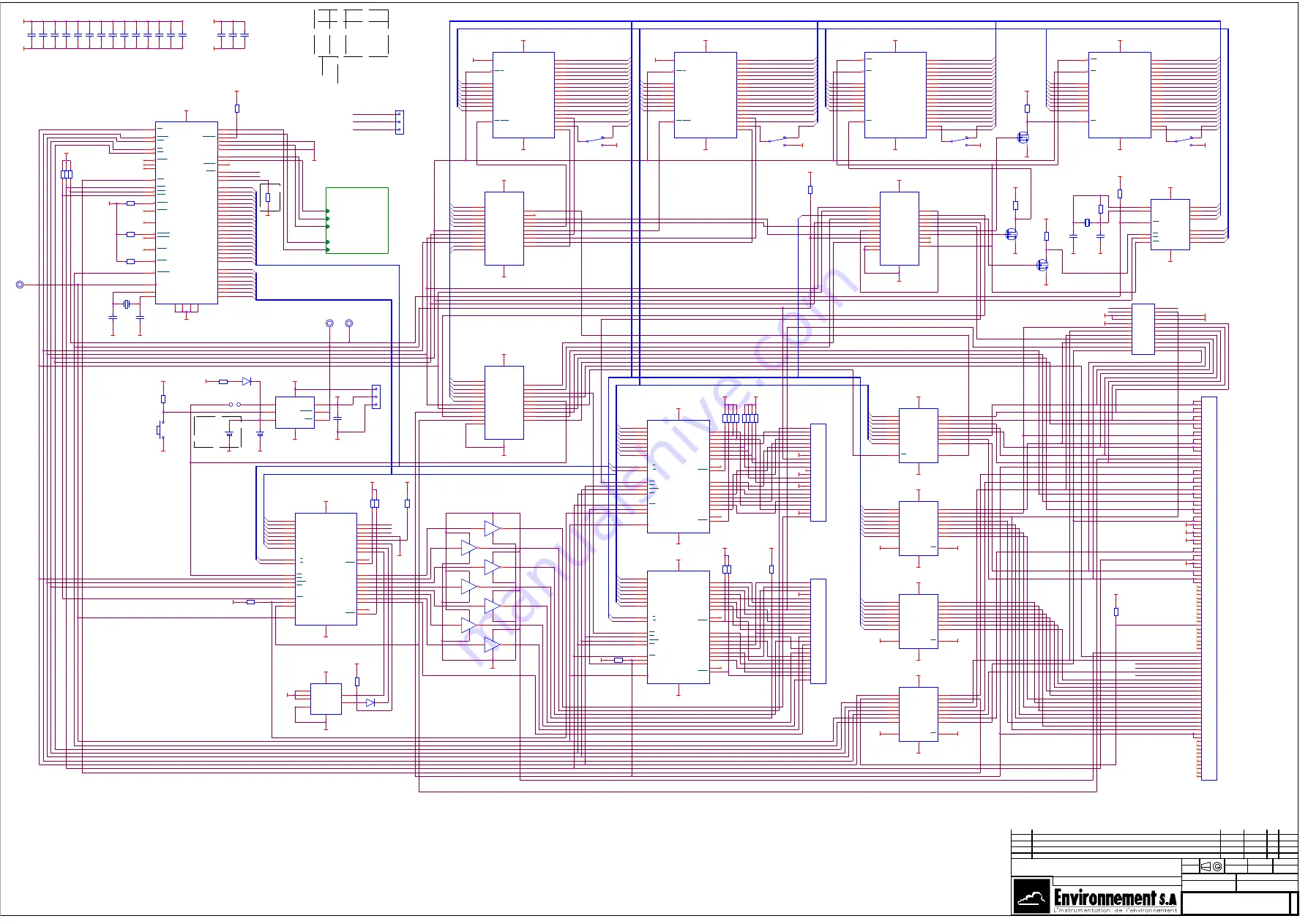
SCHEMA DE BASE / BASIC DIAGRAM

1

C03-SC0053-K

NL

15/10/03

G

F

ICHI

E

R:

CARTE MICRO -III- MICRO BOARD  

Remplacement de J2

A3

INDICE

FORMAT

N° F.M

ECHELLE

DATE

NOM

VISA

TOL. GEN.

USINE

TRAITEMENT

MATIERE

DETAILS

SCHEMA DE BASE / BASIC DIAGRAM

1

C03-SC0053-K

NL

15/10/03

G

F

ICHI

E

R:

CARTE MICRO -III- MICRO BOARD  

Remplacement de J2

A3

INDICE

FORMAT

N° F.M

ECHELLE

DATE

NOM

VISA

TOL. GEN.

USINE

TRAITEMENT

MATIERE

DETAILS

SCHEMA DE BASE / BASIC DIAGRAM

1

C03-SC0053-K

NL

15/10/03

G

F

ICHI

E

R:

CARTE MICRO -III- MICRO BOARD  

Remplacement de J2

A3

R21

47kO

R21

47kO

1

2

U16E

U16E

5

12

9

8

C8

C8

1

2

U10

Z80 PIO

U10

Z80 PIO

V

C

C

3

0

G

N

D

1

3

D0

21

D1

22

D2

1

D3

44

D4

43

D5

42

D6

3

D7

2

B/A SEL

7

C/D SEL

5

PA0

17

PA1

16

PA2

15

PA3

14

PA4

11

PA5

10

PA6

9

PA7

8

ARDY

20

ASTB

18

PB0

31

PB1

32

PB2

33

PB3

34

PB4

35

PB5

36

PB6

37

PB7

38

BRDY

23

BSTB

19

CLK

29

IEO

26

IEI

28

INT

27

RD

39

IORQ

40

M1

41

CE

4

SW 4

SW 4

2

1

3

S2

CON24C

S2

CON24C

1
2
3
4
5
6
7
8
9
10
11
12

24
23
22
21
20
19
18
17
16
15
14
13

R22

47kO

R22

47kO

1

2

R13

47kO

R13

47kO

1

2

R31

47kO

R31

47kO

1

2

R33

1k

R33

1k

1

2

U16F

U16F

6

11

9

8

C9

C9

1

2

U11

Z80 PIO

U11

Z80 PIO

V

C

C

3

0

G

N

D

1

3

D0

21

D1

22

D2

1

D3

44

D4

43

D5

42

D6

3

D7

2

B/A SEL

7

C/D SEL

5

PA0

17

PA1

16

PA2

15

PA3

14

PA4

11

PA5

10

PA6

9

PA7

8

ARDY

20

ASTB

18

PB0

31

PB1

32

PB2

33

PB3

34

PB4

35

PB5

36

PB6

37

PB7

38

BRDY

23

BSTB

19

CLK

29

IEO

26

IEI

28

INT

27

RD

39

IORQ

40

M1

41

CE

4

B1

B1

3

4

SW 3

SW 3

2

1

3

R14

47kO

R14

47kO

1

2

J3

1X3-1

J3

1X3-1

1

2

3

U16G

U16G

7

10

9

8

CN2

GESTION IMPRIMANTE

CN2

GESTION IMPRIMANTE

A01

1

A03

3

A05

5

A07

7

A09

9

A11

11

A13

13

A15

15

A17

17

A19

19

A21

21

A23

23

A02

2

A04

4

A06

6

A08

8

A10

10

A12

12

A14

14

A16

16

A18

18

A20

20

A22

22

A24

24

C10

C10

1

2

U12

Z80 PIO

U12

Z80 PIO

V

C

C

3

0

G

N

D

1

3

D0

21

D1

22

D2

1

D3

44

D4

43

D5

42

D6

3

D7

2

B/A SEL

7

C/D SEL

5

PA0

17

PA1

16

PA2

15

PA3

14

PA4

11

PA5

10

PA6

9

PA7

8

ARDY

20

ASTB

18

PB0

31

PB1

32

PB2

33

PB3

34

PB4

35

PB5

36

PB6

37

PB7

38

BRDY

23

BSTB

19

CLK

29

IEO

26

IEI

28

INT

27

RD

39

IORQ

40

M1

41

CE

4

B2

B2

1

2

Q5

BS107

TO92

Q5

BS107

TO92

1

3

2

R15

47kO

R15

47kO

1

2

U3

58274

U3

58274

AD0

9

AD1

10

AD2

11

AD3

12

V

C

C

1

6

G

N

D

8

XIN

15

XOUT

14

DB0

7

DB1

6

DB2

5

DB3

4

WR

3

RD

2

CS

1

INT

13

Q1

12.288MHz

Q1

12.288MHz

1

2

U16A

ULN2004

U16A

ULN2004

1

16

9

8

C11

C11

1

2

R19

47kO

R19

47kO

1

2

R32

1k

R32

1k

1

2

R16

47kO

R16

47kO

1

2

C1

22pF

C1

22pF

1

2

U17

24C16

U17

24C16

V

C

C

8

V

S

S

4

A0

1

A1

2

A2

3

TST

7

SCL

6

SDA

5

R20

47kO

R20

47kO

1

2

C12

C12

1

2

R17

47kO

R17

47kO

1

2

C2

22pF

C2

22pF

1

2

R26

47kO

R26

47kO

1

2

C13

C13

1

2

CN1

BUS MICRO

CN1

BUS MICRO

C01

1

C02

2

C03

3

C04

4

C05

5

C06

6

C07

7

C08

8

C09

9

C10

10

C11

11

C12

12

C13

13

C14

14

C15

15

C16

16

C17

17

C18

18

C19

19

C20

20

C21

21

C22

22

C23

23

C24

24

C25

25

C26

26

C27

27

C28

28

C29

29

C30

30

C31

31

C32

32

C33

33

C34

34

C35

35

C36

36

C37

37

C38

38

C39

39

C40

40

C41

41

C42

42

C43

43

C44

44

C45

45

C46

46

C47

47

C48

48

C49

49

S49

50

S48

51

S47

52

S46

53

S45

54

S44

55

S43

56

S42

57

S41

58

S40

59

S39

60

S38

61

S37

62

S36

63

S35

64

S34

65

S33

66

S32

67

S31

68

S30

69

S29

70

S28

71

S27

72

S26

73

S25

74

S24

75

S23

76

S22

77

S21

78

S20

79

S19

80

S18

81

S17

82

S16

83

S15

84

S14

85

S13

86

S12

87

S11

88

S10

89

S09

90

S08

91

S07

92

S06

93

S05

94

S04

95

S03

96

S02

97

S01

98

PT1

PT1

1

R18

47kO

R18

47kO

1

2

D2

1N5818

D2

1N5818

2

1

C4

22pF

C4

22pF

1

2

D1

1N4448

D1

1N4448

2

1

C14

C14

1

2

U13

74LS245

U13

74LS245

A1

2

A2

3

A3

4

A4

5

A5

6

A6

7

A7

8

A8

9

DIR

1

B1

18

B2

17

B3

16

B4

15

B5

14

B6

13

B7

12

B8

11

EN

19

G

N

D

1

0

V

C

C

2

0

R9

4.7kO

R9

4.7kO

1

2

R27

4.7kO

R27

4.7kO

1

2

C5

22pF

C5

22pF

1

2

R5

1k

R5

1k

1

2

C15

C15

1

2

PT6

Point test

PT6

Point test

1

U9

PALCE22V10

PALCE22V10

U9

PALCE22V10

PALCE22V10

V

C

C

2

4

G

N

D

1

2

CLK/I0

1

I1

2

I2

3

I3

4

I4

5

I5

6

I6

7

I7

8

I8

9

I9

10

I/O0

14

I/O1

15

I/O2

16

I/O3

17

I/O4

18

I/O5

19

I/O6

20

I/O7

21

I10

11

I11

13

I/O8

22

I/O9

23

Q2

32.768kHz

Q2

32.768kHz

1

2

U8

PALCE22V10

PALCE22V10

U8

PALCE22V10

PALCE22V10

V

C

C

2

4

G

N

D

1

2

CLK/I0

1

I1

2

I2

3

I3

4

I4

5

I5

6

I6

7

I7

8

I8

9

I9

10

I/O0

14

I/O1

15

I/O2

16

I/O3

17

I/O4

18

I/O5

19

I/O6

20

I/O7

21

I10

11

I11

13

I/O8

22

I/O9

23

R10

4.7kO

R10

4.7kO

1

2

U14

74LS245

U14

74LS245

A1

2

A2

3

A3

4

A4

5

A5

6

A6

7

A7

8

A8

9

DIR

1

B1

18

B2

17

B3

16

B4

15

B5

14

B6

13

B7

12

B8

11

EN

19

G

N

D

1

0

V

C

C

2

0

U1

Z180 CPU

U1

Z180 CPU

RXA0

49

M1

65

V

C

C

3

4

TXA0

48

CKA0/DREQ0

50

CTS0

46

RTS0

45

DCD0

47

RXA1

53

TXA1

51

CKA1/TEND0

54

RXS/CTS1

56

TXS

55

CKS

57

A0

14

A1

15

A2

16

A3

17

A4

19

A5

20

A6

21

A7

22

A8

23

A9

24

A10

25

A11

26

A12

27

A13

28

A14

29

A15

30

A16

31

A17

32

A18/TOUT

33

D0

37

D1

38

D2

39

D3

40

D4

41

D5

42

D6

43

D7

44

EXTAL

4

XTAL

3

CLK

68

MERQ

63

IORQ

62

RD

67

WR

66

RFSH

61

E

64

ST

13

RESET

8

WAIT

5

HALT

60

TEND1

59

DREQ1

58

BACK

6

BREQ

7

INT2

12

INT1

11

INT0

10

NMI

9

V

S

S

1

8

V

S

S

1

V

S

S

2

V

S

S

3

6

A19

35

TEST

52

U18

PALCE22V10

U18

PALCE22V10

V

C

C

2

4

G

N

D

1

2

CLK/I0

1

I1

2

I2

3

I3

4

I4

5

I5

6

I6

7

I7

8

I8

9

I9

10

I/O0

14

I/O1

15

I/O2

16

I/O3

17

I/O4

18

I/O5

19

I/O6

20

I/O7

21

I10

11

I11

13

I/O8

22

I/O9

23

R7

10MO

R7

10MO

1

2

C16

C16

1

2

J2

1X3-1

BAR3P

J2

1X3-1

BAR3P

1

2

3

ST1

Strap

ST1

Strap

1

2

R11

4.7kO

R11

4.7kO

1

2

U15

74LS245

U15

74LS245

A1

2

A2

3

A3

4

A4

5

A5

6

A6

7

A7

8

A8

9

DIR

1

B1

18

B2

17

B3

16

B4

15

B5

14

B6

13

B7

12

B8

11

EN

19

G

N

D

1

0

V

C

C

2

0

CN3

BUS MICRO

CN3

BUS MICRO

C01

1

C02

2

C03

3

C04

4

C05

5

C06

6

C07

7

C08

8

C09

9

C10

10

C11

11

C12

12

C13

13

S13

14

S12

15

S11

16

S10

17

S09

18

S08

19

S07

20

S06

21

S05

22

S04

23

S03

24

S02

25

S01

26

R28

47kO

R28

47kO

1

2

R4

30.1k

R4

30.1k

1

2

C17

C17

1

2

R30

10K

R30

10K

1

2

C18

C18

1

2

TRANSMISSION 232/422 ISOLE

0053F2-2

TXA1

RXA1

RTS0

TXA0

RXA0

U4

EPROM 256X8K

U4

EPROM 256X8K

V

C

C

3

2

G

N

D

1

6

A0

12

A1

11

A2

10

A3

9

A4

8

A5

7

A6

6

A7

5

A8

27

A9

26

A10

23

A11

25

A12

4

A13

28

A14

29

A15

3

A16

2

A17

30

A18

31

O3

17

O2

15

O1

14

O0

13

O4

18

O5

19

O6

20

O7

21

VPP

1

OE(G)

24

CE/PGM

22

PT5

Point test

PT5

Point test

1

U2

MAX694

U2

MAX694

VOUT

1

RESET

7

V

C

C

2

G

D

N

3

PFO

5

VBATT

8

PFI

4

WDI

6

R1

4.7kO

R1

4.7kO

1

2

C19

100nF

C19

100nF

1

2

U5

EPROM 

U5

EPROM 

V

C

C

3

2

G

N

D

1

6

A0

12

A1

11

A2

10

A3

9

A4

8

A5

7

A6

6

A7

5

A8

27

A9

26

A10

23

A11

25

A12

4

A13

28

A14

29

A15

3

A16

2

A17

30

A18

31

O3

17

O2

15

O1

14

O0

13

O4

18

O5

19

O6

20

O7

21

VPP

1

OE(G)

24

CE/PGM

22

U19

74LS245

U19

74LS245

A1

2

A2

3

A3

4

A4

5

A5

6

A6

7

A7

8

A8

9

DIR

1

B1

18

B2

17

B3

16

B4

15

B5

14

B6

13

B7

12

B8

11

EN

19

G

N

D

1

0

V

C

C

2

0

R12

4.7kO

R12

4.7kO

1

2

R23

47kO

R23

47kO

1

2

R8

100k

R8

100k

1

2

BP1

BP1

1

2

C20

C20

1

2

U6

RAM STATIQUE 128X8

U6

RAM STATIQUE 128X8

V

C

C

3

2

G

N

D

1

6

A0

12

A1

11

A2

10

A3

9

A4

8

A5

7

A6

6

A7

5

A8

27

A9

26

A10

23

A11

25

A12

4

A13

28

A14

3

A15

31

A16

2

A17

30

A18

1

O3

17

O2

15

O1

14

O0

13

O4

18

O5

19

O6

20

O7

21

OE

24

CS

22

WE

29

R24

R24

1

2

C21

C21

1

2

U7

RAM STATIQUE 128X8

U7

RAM STATIQUE 128X8

V

C

C

3

2

G

N

D

1

6

A0

12

A1

11

A2

10

A3

9

A4

8

A5

7

A6

6

A7

5

A8

27

A9

26

A10

23

A11

25

A12

4

A13

28

A14

3

A15

31

A16

2

A17

30

A18

1

O3

17

O2

15

O1

14

O0

13

O4

18

O5

19

O6

20

O7

21

OE

24

CS

22

WE

29

R25

47kO

R25

47kO

1

2

C22

C22

1

2

U16B

U16B

2

15

9

8

Q4
BS107

TO92

Q4
BS107

TO92

1

3

2

C3

100nF

C3

100nF

1

2

SW 1

SW 1

2

1

3

R2

4.7kO

R2

4.7kO

1

2

U16C

U16C

3

14

9

8

R34

1k

R34

1k

1

2

C6

100nF

C6

100nF

1

2

SW 2

SW 2

2

1

3

R35

46,4K

R35

46,4K

1

2

R29

47kO

R29

47kO

1

2

Q3
BS107

TO92

Q3
BS107

TO92

1

3

2

R3

4.7kO

R3

4.7kO

1

2

U16D

U16D

4

13

9

8

C7

C7

1

2

Summary of Contents for Envea MIR 9000

Page 1: ...TECHNICAL MANUAL MIR 9000 LCD MULTIGAS ANALYZER MARCH 2018 111 Bd Robespierre 78300 POISSY FRANCE TEL 33 1 39 22 38 00 FAX 33 1 39 65 38 08 http www environnement sa com...

Page 2: ...ed 0 2 JULY 2009 WARNING The information in this document is subject to change without notice The designer reserves the right to upgrade his equipment without updating this document Consequently the i...

Page 3: ...PLIED TO THE MIR 9000 2 4 2 3 DESCRIPTION OF THE MAIN MODULES 2 8 2 4 SIMPLIFIED OPERATION FLOWCHART 2 13 CHAPTER 3 OPERATING INSTRUCTIONS 3 1 FIRST TIME RUNNING 3 4 3 2 PROGRAMMING THE MIR 9000 3 6 3...

Page 4: ...ARMS AND CONTROLS 5 3 5 2 ADJUSTMENT AND INSPECTION OF THE MOTHERBOARD 5 12 5 3 ADJUSTMENT AND INSPECTION OF THE MIR NH3 H2O VERSION 5 19 5 4 CONFIGURING THE BOARDS 5 26 CHAPTER 6 BREAK DOWN AND LOCAT...

Page 5: ...21 D 1 3 DAC 4 8 BOARD BASIC DIAGRAM C02 SC0121 D 2 3 DAC 4 8 BOARD BASIC DIAGRAM C02 SC0121 D 3 3 MOTOR CONTROL BOARD DIAGRAM C02 S2 0215 C 1 1 MICRO III BOARD BASIC DIAGRAM C03 SC0053 K 1 2 MICRO II...

Page 6: ...ion links 1 16 Figure 1 11 Dimensions of the MIR9000 fixed tight box version 1 18 Figure 1 12 Dimensions of the MIR Rack version 1 19 Figure 2 1 Infrared absorption 2 2 Figure 2 2 MIR 9000 NH3 H2O opt...

Page 7: ...R NH3 H20 version 5 22 Figure 5 13 Detector signal Oscillogram MIR NH3 H20 version 5 22 Figure 5 14 Detector signal Oscillogram MIR NH3 H20 version 5 23 Figure 5 15 Sampling Oscillogram MIR NH3 H20 ve...

Page 8: ...22 07 2009 3 23 07 2009 3 24 07 2009 3 25 07 2009 3 26 07 2009 3 27 07 2009 3 28 07 2009 3 29 07 2009 3 30 07 2009 3 31 07 2009 3 32 07 2009 3 33 07 2009 3 34 07 2009 3 35 07 2009 3 36 07 2009 3 37 0...

Page 9: ...2009 6 15 07 2009 6 16 07 2009 6 17 07 2009 6 18 07 2009 6 19 07 2009 6 20 07 2009 6 21 07 2009 6 22 07 2009 7 1 07 2009 7 2 07 2009 7 3 07 2009 7 4 07 2009 7 5 07 2009 7 6 07 2009 7 7 07 2009 7 8 07...

Page 10: ...Duplication prohibited MIR 9000 EnvironnementS A 0 10 JULY 2009 Page intentionally left blank...

Page 11: ...16 1 2 3 2 Dimensions and weight Figure 1 11 and Figure 1 12 1 19 1 2 3 3 Handling and storage 1 20 Figure 1 1 Presentation of the MIR 9000 analyzer 1 2 Figure 1 2 Display and keyboard 1 4 Figure 1 3...

Page 12: ...EnvironnementS A MIR 9000 Duplication prohibited 1 2 JULY 2009 1 GENERAL CHARACTERISTICS Figure 1 1 Presentation of the MIR 9000 analyzer...

Page 13: ...d on the front panel optional analog outputs an optional digital output When the analyzer is connected to a SEC probe it can be used for various applications and in particular for The monitoring of co...

Page 14: ...front panel of the MIR 9000 is fitted with A backlit liquid crystal display Figure 1 2 16 lines 40 columns 240 128 pixels It provides the measurement values according to the selected unit and the inf...

Page 15: ...ited MIR 9000 EnvironnementS A 1 5 JULY 2009 The keyboard with 6 sensitive keys The control and check functions of the unit are controlled through the keyboard The function of each key varies with the...

Page 16: ...to TIG 8 60 conductor from the analog digital and logic outputs 9 RJ45 socket Figure 1 3 Lower panel of the MIR 9000 fixed tight box version 1 sample outlet 2 heated line 3 air inlet 7 mains power sup...

Page 17: ...ital and logic outputs towards the interface board A 13 mm packing box 6 enables the passing of the mains power supply cable A RJ45 socket 9 used for Ethernet connection 1 1 2 2 2 NH3 H2O option tight...

Page 18: ...closure 7 power supply 8 motherboard 9 automaton microprocessor board 10 optional DAC8 board 11 DAC8 board 12 display microprocessor and interface board ARM7 board 16 RS4i board 18 O2 sensor 19 pressu...

Page 19: ...al screws at the front need to be loosened and the upper cap needs to be drawn back in order to have access to the inside components 1 1 2 3 1 Tight box version Figure 1 5 Solenoid valve unit 1 Pump 2...

Page 20: ...d gaseous correlation wheel 4 optical bench 5 optical bench enclosure 6 motherboard 7 automaton microprocessor Micro3 board 7 8 optional DAC8 board 9 DAC8 board 11 display microprocessor and interface...

Page 21: ...4 Ejector on the optical bench Flowmeter under the optical bench 1 1 3 VARIOUS OPERATION MODES 1 1 3 1 Standard Expression of measurement values in ppm mg m3 or as Reference zero zero and automatic ca...

Page 22: ...EnvironnementS A MIR 9000 Duplication prohibited 1 12 JULY 2009 Figure 1 7 Analysis cabinet...

Page 23: ...itioned analysis cabinet Figure 1 7 that consists of A unit for conditioning and distributing compressed air M D S An electrical distribution unit A box for automatic gas commutation TIG with electric...

Page 24: ...EnvironnementS A MIR 9000 Duplication prohibited 1 14 JULY 2009 Figure 1 8 Example of application...

Page 25: ...h SEC probe 1 l min approximately with dilution unit Sample temperature 0 C Temp 70 C at the inlet of the analyzer Maximum sample dew point 0 C with SEC probe 50 C with dilution unit Display LCD 240 1...

Page 26: ...igital inputs outputs 230V 50Hz 100V 60Hz Mains power supply A CQUISITION SYSTEM NOx NO converter Drier and filtering module SEC probe Sample Vent Zero air Zero air Span Span Remote controls SEC probe...

Page 27: ...Duplication prohibited MIR 9000 EnvironnementS A 1 17 JULY 2009 Page intentionally left blank...

Page 28: ...EnvironnementS A MIR 9000 Duplication prohibited 1 18 JULY 2009 Figure 1 11 Dimensions of the MIR9000 fixed tight box version...

Page 29: ...2 3 1 1 Dimensions and weight Figure 1 11 and Figure 1 12 Figure 1 12Fixed tight box version Depth 260 mm Width 400 mm Height 735 mm Weight 24 kg 1 2 3 1 2 Rack version Depth 655 mm Width 483 mm Heig...

Page 30: ...d with care in order to avoid the damaging of the various connectors and connections sticking out from the backside or the lateral side Make sure that the fluid inlets outlets of the monitor are fitte...

Page 31: ...ECTRONIC BOARDS 2 10 2 3 3 1 The motherboard 2 10 2 3 3 2 The MICRO III microprocessor board 2 10 2 3 3 3 The ARM7 board 2 11 2 3 3 4 The RS4i serial link communication board 2 11 2 3 3 5 Analog outpu...

Page 32: ...2 2 JULY 2009 2 OPERATION IR source Optical filters Gaseous cells Measurement chamber Detector Figure 2 1 Infrared absorption IR source Optical filters Gaseous cells Measurement chamber Detector Figur...

Page 33: ...n the gas and the wavelength L is the length of the optical path C is the concentration Since there is not just one wavelength behind an interference filter but several wavelengths the equation become...

Page 34: ...is ratio is now only 1 15000 which proves its efficiency However for some gases only a simple optical reference filter is used for correlation It is centred on a wavelength that is not absorbed by the...

Page 35: ...Duplication prohibited MIR 9000 EnvironnementS A 2 5 JULY 2009 Page intentionally left blank...

Page 36: ...SV PUMP IR source RS4i board Micro board DAC8 board ANALOG LOGIC AND NUMERIC LINKS POWER SUPPLY MAINS IR DETECTOR MEASUREMENT CHAMBER MOTOR CORRELATION WHEEL MOTHER BOARD INTERFACE MICRO BOARD ELECTR...

Page 37: ...MOTOR MOTHER BOARD POWER SUPPLY MAINS IR source POWER CONTROL BOARDS DISPLAY KEYBOARD MICRO BOARD DAC8 BOARD ANALOG LOGIC AND DIGITAL LINKS IR DETECTOR MOTOR OF FILTERS WHEEL FLOW SENSOR ELECTRIC SIG...

Page 38: ...icroprocessor board and the analog output boards are plugged in A LCD microprocessor board for the management of parameters LCD display and serial output board An intake pump replaced in the NH3 H2O o...

Page 39: ...Duplication prohibited MIR 9000 EnvironnementS A 2 9 JULY 2009 Figure 2 5 Basic fluid diagram of MIR9000...

Page 40: ...tor is a semiconductor with a high detection level cooled by Peltier effect In the NH3 H2O option the analyzer is equipped with a correlation wheel for the gaseous cells close to the IR source and wit...

Page 41: ...the analyzer backups the software re loading and the instantaneous measurements acquisition REMARK In the CONFIGURATION menu the USB Flash Drive item is only displayed if a USB flash drive is connecte...

Page 42: ...0 1 V 0 10 V 0 20 mA 4 20 mA It is possible to install a second DAC8 board 2 3 3 6 LCD Interface board It ensures the keyboard inputs and the LCD display It is integrated into the ARM7 board 2 3 3 7...

Page 43: ...ON CALCULATION AND MEASUREMENT MANAGEMENT INTERFERENCES CORRECTIONS CONCENTRATION CALCULATIONS ACQUISITION OF ANALOG INPUTS PROCESSING OF THRESHOLD OVERSHOOT ALARMS CHECK MANAGEMENT OF AUTOMATIC CYCLE...

Page 44: ...EnvironnementS A MIR 9000 Duplication prohibited 2 14 NOVEMBER 2014 Page intentionally left blank...

Page 45: ...6 3 2 2 1 Programming the numerical parameters 3 6 3 2 2 2 Programming the parameters to be configured via a pull down list 3 6 3 3 DESCRIPTION OF THE SCREENS 3 8 3 3 1 MAIN MENU 3 8 3 3 2 MEASUREMENT...

Page 46: ...generation 3 53 3 4 1 2 Generation of span gas 3 53 3 4 1 3 Use of the automatic cycles 3 53 3 4 2 CALIBRATION 3 54 3 4 2 1 Necessary material 3 54 3 4 2 2 Procedure 3 54 3 4 3 SPECIFIC ARRANGEMENT F...

Page 47: ...15 14 16 Ground or Opto ground manometer 10 9 8 7 6 5 4 3 2 1 11 12 13 15 14 16 17 18 19 20 21 Common span contact Output span contact Input air default manometer Ground or opto ground stand by Input...

Page 48: ...or will disturb the cut out power supplies 3 1 2 2 Signal connections Connect the analog outputs see configuration and calibration DAC 8 Chapter 5 Connect the logic inputs outputs Connect the serial l...

Page 49: ...the back of the rack on the sector filter block The analyzer moves into the WARM UP mode and then makes a reference zero The condition for leaving the WARM UP mode is that the adjustment temperature o...

Page 50: ...ens on a serial printer or capturing them in a text file The communications serial port should be configured in advance with the PRN protocol in the Configuration Serial link menu 3 2 2 PROGRAMMING TH...

Page 51: ...Printout Alarms display Factors Select gas Cycles Analog Inputs Date Time Language Measurement mode Offset Conversion General correction Selection Printer output Optical Bench Absorption MUX signals D...

Page 52: ...ion prohibited 3 8 JULY 2009 3 3 DESCRIPTION OF THE SCREENS 3 3 1 MAIN MENU This is the top level menu It enables access to all the analyzer s menus and sub menus Select the menu with the or keys and...

Page 53: ...kinds of display Select the menu with the or key and confirm the selection with the key 3 3 2 1 Instantaneous This display is the default when the analyzer is started up The instantaneous measurements...

Page 54: ...N input It becomes highlighted after acknowledgement see also TIG OPTION Ref Z This starts a Zero Reference cycle It becomes highlighted during the first dead time Only if there are more than 3 measur...

Page 55: ...is activated in this case by pressing the F3 key It is already configured To activate the ZERO PROBE mode select the PROBE mode using the F4 key and confirm the function using the F3 key To activate...

Page 56: ...activated The user can then consult the type of control to be made by selecting the Measurement Alarms Display menu The TM1 xxxx sec counter appears at the top right when a zero reference is started I...

Page 57: ...s of 8 is displayed in single height The period for calculating the average values is defined in the Stored data Selection menu Keys Identical to the display of the Measurement Instantaneous menu Apar...

Page 58: ...following parameters are found in this menu Flowrate IR source voltage Motor speed Clamp voltage PELTIER current Optical bench temperature Pressure These values have to be compared with data shown on...

Page 59: ...ges Units menu When the representation is complete the graph starts from scratch Graphics can be visualized for 16 minutes Keys Identical to the display of the Measurement Instantaneous menu The key e...

Page 60: ...ed on the communications port to be PRN This protocol is declared in the Configuration Serial link menu Remark When the rate is 0000 the screen is displayed when a character is received on the selecte...

Page 61: ...f alarms Automaton link General Air Top Synchro Probe temperature SEC probe option Probe pressure SEC probe option Low level energy Optical temperature Clamp voltage IR source supply Peltier current S...

Page 62: ...shold control X Channel number Flowrate check Pressure check A control indicates a potential problem for the analyzer which should receive a maintenance operation The measurement remains valid NOTE Th...

Page 63: ...s well as the adjustment of the analyzer s internal cycles 3 3 3 1 Factors This enables adjusting the span coefficient of the gas The Delta K enables knowing the distance between 2 successive K span v...

Page 64: ...2009 3 3 3 2 Select gas This menu is only for user information to remind him of the span gas concentrations used for the calibration of the analyzer TIG OPTION The number of the solenoid valve of EV1...

Page 65: ...ramming of the reference cycles 03 H for the period 90 sec for the duration 240 sec for the dead time NOTE The minimum duration of any cycle is 60 sec The Last State variable makes it possible to sele...

Page 66: ...A MIR 9000 Duplication prohibited 3 22 JULY 2009 3 3 3 4 Analog inputs Optionnal This screen only appears if analog inputs are declared The user may modify the calibration coefficient of the programme...

Page 67: ...on has been activated in the factory configuration menu The MIR STD v3 2 menu gives access to the factory configuration it is protected by a sequence of keys within this menu It corresponds to the AUT...

Page 68: ...t K dilution The Special gas and Special Ana options make it possible to create a specific name for a measurement channel and an analog input The AUTOMATE field makes it possible to identify the versi...

Page 69: ...lated and displayed in mg m3 Unit ppm mg m3 mg Nm3 0 ppmCH4 ppm C mV mA C hPa l h mmHg g m3 m s Nm3 h KNm3 h DEG W m2 The measurement format is selected in this menu The selection is determined accord...

Page 70: ...surement and check any possible drift The format is in the XXX X form The value of the Conversion parameter is used for the ppm mg m3 calculation A default value is defined when creating each paramete...

Page 71: ...concentration of CO2 and to the sample gas pressure Calculations made for each correction Correction of H2O Measurement corrected Measurement x 100 100 Measurement H2O Correction of O2 Measurement co...

Page 72: ...n of the relays Disable Value Limit 1 Value Limit 1 Value Limit 2 Value Limit 2 CAUTION The zero relay forces the analyzer into zero mode In this case no measurement is made on the sample gas To exit...

Page 73: ...only appears when the DTP option is activated in the factory configuration It enables defining the five parameters ruled by the DTP option Chimney flowrate Chimney temperature Chimney pressure Gas spe...

Page 74: ...of the screen is common to each of the parameters The K Pitot coefficient corresponds to the coefficient of the Pitot tube itself in use usual coefficient 0 75 The Mass vol parameter corresponds to th...

Page 75: ...o communications ports The configuration is as follows Address Transmission speed Format Protocol Speeds that can be used 600 1200 2400 4800 9600 19200 57600 Formats that can be used 8 n 1 8 o 1 8 e 1...

Page 76: ...adjustment parameters factory configuration for the maintenance of the analyzer The Stepping motors and Analog inputs menus are proposed when these options have been confirmed in the Analyzer configu...

Page 77: ...n each of the signals and is calculated so as to adjust the most important signal to the number of points defined in the Auto Gain variable The programmed value is then in the form 50 001 Optical benc...

Page 78: ...red The names of the gases are chosen from among HCL SO2 NO CO CO2 H2O NO2 NOX CH4 HC COT TOC COV VOC HCT N2O NH3 HF ABS COR1 COR2 D2 SPEC NOTE The label of the SPEC parameter can be modified in the C...

Page 79: ...gnals appear in the Tests Optical bench menu Note the ratio of the signals during a zero reference corresponds to the SSR0 value Inter Correct makes it possible to program the number of interference c...

Page 80: ...00 120 140 160 180 200 0 2 4 6 8 10 12 14 16 18 20 Absorption Concentration Seg 2 Seg 5 Seg 4 Seg 3 Seg 1 Pt 1 Pt 2 Pt 3 Pt 4 Pt 5 Figure 3 4 Example of a linearization curve from five polynomials 3 3...

Page 81: ...ding to the absorption of the selected channel Interferant parameter Cn Ab Correction of the absorption measured according to the concentration of the selected channel Interferant parameter An Cn Corr...

Page 82: ...wns in the analyzer or wrong measurements This screen enables adjusting the sequences of oscillations of the step by step motor while the analyzer is configured for the measurement of NH3 NH3 Mode opt...

Page 83: ...e key also makes it possible to visualize the following analog input Analog Input Name gives the name of the analog input The names of the analog inputs are chosen from among O2 PRES DEB FLOW TEMP POU...

Page 84: ...this parameter makes it possible to hide the measurement for example in the case of a channel being used for the correction of others only Latch This parameter determines if the measure is blocked dur...

Page 85: ...ters Low range High range NOTE For a sample flow of 20 l h and 90 l h in zero application with Sec Probe the flowrate graph is defined between 0 and 40 or 60 l h In addition the thresholds of CONTROL...

Page 86: ...atically recorded in the chosen memorisation period Autonomy of Storage depends of the total number of measurements and the calculation according to the formula 200K 1024 total number of measurements...

Page 87: ...ohibited MIR 9000 EnvironnementS A 3 43 JULY 2009 3 3 5 1 Selection The measurements stored can be re read by using the serial link ONLY with the aid of appropriate software or the printing function d...

Page 88: ...ered data 19 05 1999 13 35 0000 H2O 5 40 ppm SO2 5 46 ppm NO 4 53 mg Nm3 CO2 5 10 MX16 0 14 mv 19 05 1999 13 36 0000 H2O 5 38 ppm SO2 5 45 ppm NO 4 56 mg Nm3 CO2 5 15 MX16 0 14 mv 19 05 1999 13 37 000...

Page 89: ...asurement channel the main signals and intermediate values so that the measured concentration can be determined These information are used to control the signals during maintenance Keys The Sample Zer...

Page 90: ...signal on the reference signal S SR SSR0 ratio of the measurement signal on the reference signal during the last zero reference NOTE The value SSR0 is used to manage the Ratio Check Rx fault by compar...

Page 91: ...orptions and also concentrations and corrected concentrations cf Optical Bench menu The display is in single height making it possible to visualize up to 12 measurements on this screen Keys The Sample...

Page 92: ...are in millivolts with the exception of the PELTIER current expressed in milliamperes The DTP1 to DTP4 values correspond to the 4 supplementary analog channels inserted on the interface 2 board NOTE...

Page 93: ...2nd card in option All the DAC channels from 1 to 16 are commanded simultaneously The measurements are restored when leaving the test Keys 0 Adjustment of the start of the scale 4095 Adjustment of the...

Page 94: ...inputs inform about the current state This menu makes it possible to verify that the remote commands are read correctly solenoid valves Span 1 to Span 5 of the TIG option selection of the Probe Analyz...

Page 95: ...o possible to access to all the screens while remaining in stand by The STAND BY message appears on the measurement screens Re start up of the analyzer is made by returning to the measurement menu and...

Page 96: ...d application In certain conditions taking into account the analyzer s low drift a six monthly control is sufficient Calibration It is a procedure to correct the analyzer s response at a scale point s...

Page 97: ...s approximately equal to either the value measured regularly or the limit value imposed by the local regulations The bottle used should be certified regularly according to the user s quality assurance...

Page 98: ...select the ZERO ANALYZER mode MIR NH3 H2O version select the ZERO ANALYZER mode Control of the scale point First of all make a zero control Select the input to which the gas is connected using the mes...

Page 99: ...HCl HF and NH3 Figure 3 7 HCl calibration Put the analyzer into zero mode by pressing the z ro key TIG Option and MIR NH3 H2O version select the SPAN PROBE mode Open the bottle of nitrogen and adjust...

Page 100: ...trogen TIG Option and MIR NH3 H2O version select the SPAN PROBE mode 3 4 3 2 Calibration of HCl and NH3 by comparison The HCl and NH3 calibrations can be made by comparing the measurement of the MIR 9...

Page 101: ...onnementS A 4 1 JULY 2009 CHAPTER 4 PREVENTIVE MAINTENANCE 4 1 SAFETY INSTRUCTIONS 4 3 4 2 MAINTENANCE CALENDAR 4 4 4 3 MAINTENANCE OPERATION SHEETS 4 4 4 4 EQUIPMENT REQUIRED FOR MAINTENANCE 4 16 Fig...

Page 102: ...EnvironnementS A MIR 9000 Duplication prohibited 4 2 JULY 2009 Page intentionality left blank...

Page 103: ...no leaks in the pipes Competent personnel only are allowed to carry out operations on the analyzer Concerning safety the manufacturer disclaims his responsibility in case of unqualified personnel usin...

Page 104: ...er site in a precise way The interval between two visits is usually 1 month Nature of the operations Frequency Sheet no Replacing the dust filters 1 month 4 3 1 Inspection of all metrological paramete...

Page 105: ...ons or when the flows have decreased NH3 H2O version of the MIR Antidust filter SWAGELOK type Ref SS F MM 7 Location under the measurement chamber upper heating plate Dismantle the filter and replace...

Page 106: ...nitor is functioning read the analog values of the MUX signals the motor speed and the Peltier current using the test2 key In particular 02 03 06 11 12 13 14 15 and 16 Intervene when the values are be...

Page 107: ...ains When the monitor is functioning in zero mode after a reference zero read the values of the gains CAG and of the signals for each position CAN of the Test Optical Bench menu DATE CAN CAG SIGNAL CA...

Page 108: ...en the 4 screws 19 and remove the head of the pump make sure that the articulation washer is not mislaid 20 Disassemble the various parts starting with part 16 Check the condition of the valves 15 Rep...

Page 109: ...ion prohibited MIR 9000 EnvironnementS A 4 9 JULY 2009 MAINTENANCE SHEET Serial no MONITOR OPERATION SHEET 4 3 3 Subject Inspection of the pump PAGE 2 2 Frequency 6 months Figure 4 1 Exploded view of...

Page 110: ...essure is less than 10 x 103 hPa Also check the guarantee limits of the gas in the cylinders Compressor Purge the capacity if necessary see user manual of the compressor for maintenance if necessary o...

Page 111: ...230V from the pump J6 The pressure drop should not decrease if the tightness is correct Otherwise check the fluid system connections seals pump etc b Zero inlet Proceed as for a this time by plugging...

Page 112: ...source block It can be necessary to disconnect additional connectors Free the measurement chamber from the optical compartment but not completely Loosen the 4 knurled fastening screws from the IR sour...

Page 113: ...nnectors and the connections between the optical forks and the stepping motor control from the IR source block It can be necessary to disconnect additional connectors Free the measurement chamber from...

Page 114: ...2 knurled fastening screws and remove the clamp Free the measurement chamber from the optical compartment and disconnect the 2 Isoversinic tubes Carefully mark their respective positions NH3 H2O MIR...

Page 115: ...old K new Reading of analyzer after calibration Date Type of operation Gas Concentr Unit Reading of analyzer before calibration K old K new Reading of analyzer after calibration Date Type of operatio...

Page 116: ...05 0226 A 5 m syringue filter 25mm dia 10 00 MAINTENANCE KIT FOR MIR RACK 1 YEAR REF DESIGNATION MIR9R K Maintenance kit for MIR rack 1 year This kit is composed of Qty F05 0226 A 5 m syringue filter...

Page 117: ...z LEVEL 2 SPECIFIC PARTS REF DESIGNATION D01 0035 H 220V laminar heater with cable D01 0742 A Laminary heater w cable C02 C2 0121 D DAC 4 CHANNELS OUTPUT BOARD C02 C1 0121 D DAC 8 CHANNELS OUTPUT BOAR...

Page 118: ...Hz F01 430 04 189 T40 220V 50Hz 10W bobbin T08 106 8H VORTEX tube MAINTENANCE KIT FOR O2SENSOR REF DESIGNATION A02 K R0007 A Maintenance kit for O2sensor This kit contains Qty 1 F02 KGZ 10 Oxygen prob...

Page 119: ...URCE 5 12 5 2 4 ADJUSTMENT OF THE PELTIER CURRENT 5 12 5 2 5 ADJUSTMENT OF THE MOTOR SPEED 5 13 5 2 6 ADJUSTMENT OF THE AMPLIFICATION CHAIN 5 13 5 3 ADJUSTMENT AND INSPECTION OF THE MIR NH3 H2O VERSIO...

Page 120: ...20 version 5 21 Figure 5 12 Detector signal Oscillogram MIR NH3 H20 version 5 22 Figure 5 13 Detector signal Oscillogram MIR NH3 H20 version 5 22 Figure 5 14 Detector signal Oscillogram MIR NH3 H20 ve...

Page 121: ...ations problem between the automaton micro board and the LCD micro board Check the link between the two micro boards connectors J2 and J3 The LD1 diode of the automaton micro board flashes if the comm...

Page 122: ...ard The rotation detection system is faltering Check the J9 and J17 connections Check the signals at PT9 and PT13 cf Checking the optical forks If the signals do not correspond change the optical fork...

Page 123: ...of dampness on the inside Probe pressure The analyzer is linked to a SEC probe The dry air pressure is outside the limits 800mb Pe Check the pressure of the compressed air 4 bars Check the SEC probe...

Page 124: ...e is too low it will not be possible for the analyzer to reach its given temperature Temperature 45 C SEC probe Temperature 97 C dilution module Check whether the red LED on the motherboard is flashin...

Page 125: ...reference If the adjustment cannot be made Check that the internal temperature of the analyzer is not higher than the correct one Check the connections of the 2 2 resistance and of the transistor on J...

Page 126: ...he measurement is higher than the threshold value Software Pressure Flow menu Analyzer Pressure Check if the measurement is lower than the threshold value The threshold values are shown on the control...

Page 127: ...rammed for the X parameter After a Zero Reference check in Zero mode the signals and gains Tests Optical Bench menu Calculate the new wheel ratio as shown below signal measurement signal reference X 1...

Page 128: ...ion Check the 4A fuse of the cut out feed Check the feeds 15V and 5V cf Adjustment and inspection of the motherboard If necessary adjust the 5V Control 15V 15V supply outside the limits Compare the va...

Page 129: ...yzer works with a SEC probe Problem with drying efficiency on the SEC probe Check the following points A Check the pressure of the compressed air 4 bars and the efficiency of the ejector of the SEC pr...

Page 130: ...lt 5 2 1 3 Power supply 5 Volts The voltage measured between Pt 4 and Pt 25 should be 5100 mV 100 mV This voltage can be adjusted on the supply board using potentiometer VI As this supply is protected...

Page 131: ...signals a double trace oscilloscope is required The grounds of the probes should be connected to point Pt 25 of the motherboard 5 2 6 1 Control of the optical forks Signal chopper optical fork Connec...

Page 132: ...id of the positioning of the optical forks After releasing the two screws holding it in place remove the optical forks assembly until the sampling is centered on the high levels Refasten the two screw...

Page 133: ...n 5 2 6 3 Adjustment of the clamp The clamp signal is measured in Pt 12 The length of the pulse will be adjusted to 0 6 ms 0 05 ms using potentiometer P4 In order to visualize this signal in relation...

Page 134: ...tion Figure 5 7 Clamp signal Oscillogram 3 If the adjustment of the clamp is bad because the clamp is overstepping on the low to high transition of the detector signal it is still possible to adjust t...

Page 135: ...menu adjust the Static Gain variable to 200 fixed gain at 200 Start a ZERO REF cycle Once the ZERO REF cycle has ended put the analyzer in ZERO mode in ZERO ANALYZER mode with the TIG option The basel...

Page 136: ...Auto Gain variable corresponds to this value rounding down the value to the next 10 000 place for example if the largest signal is at 56800 points it will take the value at 50 000 pts In the Configur...

Page 137: ...ests Optical Bench menu multiplied by 100 This value should be programmed in the Configuration Software Channels setting menu to the Wheel Ratio variable 5 3 ADJUSTMENT AND INSPECTION OF THE MIR NH3 H...

Page 138: ...the optical path FILTER 03 in our example and in REFERENCE one specific optical filter is placed on the optical path FILTER 04 in our example The parameters of this menu enable configuring the acquisi...

Page 139: ...ING THE DETECTOR SIGNAL Connect the probe of the oscilloscope to Pt 0 order to visualize the signal Complementary information is given by the optical fork signal in Pt 9 The motor speed is adjusted by...

Page 140: ...oo low In this example the motor speed is close to 550 turns per minute Figure 5 12 Detector signal Oscillogram MIR NH3 H20 version INCORRECT The speed of the motor is too high In this example the mot...

Page 141: ...the signals and the probe 2 to Pt 19 to visualize the sampling Use the inverse function of the oscilloscope for channel 2 The sampling on the low level of the signal should be centered and adjusted a...

Page 142: ...5 24 JULY 2009 INCORRECT Electronic sampling is made too far to the right of the high level and in the descending part of the signal Figure 5 16 Sampling Oscillogram MIR NH3 H20 version CORRECT Figur...

Page 143: ...the S signal and the reference position corresponds to the SR signal The maximum value of the signal is 65535 pts saturation AD 16 bits 5 3 5 2 Searching for the saturation line Make sure that the os...

Page 144: ...a TIG 1 board a strap should be placed on the CN2 connector of the Micro 3 board between pin22 and pin23 5 4 3 INTERFACE 2 BOARD This board is similar to the interface 1 board The main modification co...

Page 145: ...s connected to the motherboard by a 26 point cable J 31 connector on the motherboard to the interface 2 board by a 3 point cable J 19 connector to the mains 230 or 100 V for the solenoid valves comman...

Page 146: ...EnvironnementS A MIR 9000 Duplication prohibited 5 28 JULY 2009 Figure 5 18 Motherboard configuration...

Page 147: ...ith pressure sensor Without pressure sensor Jumper references Symbols Nature of operation ST17 With GND pressure sensor Without pressure sensor ST18 Remote control Zero Ref Not used ST19 Interface 2 b...

Page 148: ...EnvironnementS A MIR 9000 Duplication prohibited 5 30 JULY 2009 Figure 5 19 Test points and settings of the motherboard...

Page 149: ...PT14 Cubicle temperature PT15 Cubicle temperature before buffer PT16 IR source supply voltage PT17 AD input PT18 Pressure PT19 RUN test PT20 STATUS test PT21 Flow test or EXT 3 PT22 Wheel motor power...

Page 150: ...EnvironnementS A MIR 9000 Duplication prohibited 5 32 JULY 2009 Figure 5 20 Configuration and settings of the DAC8 board...

Page 151: ...mA referenced to 15V max charge 1200 isolator 0 10V 0 10V 0 1V 0 1V P5 Zero setting P7 Zero setting P6 Gain setting P8 Gain setting ANALOG OUTPUT No 5 ANALOG OUTPUT No 6 ST13 ST14 ST15 SW5 FUNCTION ST...

Page 152: ...LY 2009 SW1 SW2 SW3 SW4 SW5 SW6 SW7 ST2 ST3 ST4 ST1 Jumper references Symbols Function SW1 2Mb version 256KX8 SW2 2Mb version 256KX8 SW3 2Mb version 256KX8 SW4 2Mb version 256KX8 SW5 SW6 SW7 RS232 SW5...

Page 153: ...ces Strapped positions Nature of operation ST1 standard configuration ST2 standard configuration SW1 standard configuration SW2 standard configuration SW3 standard configuration S1 ON 1 2 3 4 standard...

Page 154: ...6 JULY 2009 Jumper references Strapped positions Nature of operation SW1 standard configuration ST8 SW1 ST7 ST6 ST5 ST4 ST3 ST2 ST1 IR source motor block ST3 ST7 Detector motor block ST4 ST8 Figure 5...

Page 155: ...CATION 6 1 HCL DISTRIBUTION MODULE 6 2 6 2 PUMP 6 4 6 3 OPTICAL BENCH 6 6 6 4 OXYGENE PROBE 6 9 6 5 APPENDIX 6 11 6 5 1 ARM7 BOARD 6 11 6 5 2 CONFIGURATION OF RS4I BOARD 6 11 Figure 6 1 HCl distributi...

Page 156: ...ore 1 9 Viton G06 007 2 1 9 V 2 3 C type fitting for cylinder P02 1067 A 1 4 O ring seal int tore 10 5 2 7 Viton G06 010 5 2 7 V 1 5 Stopper for fitting of cylinder P06 0955 A 1 6 Small chain with 20...

Page 157: ......

Page 158: ...d 1 8 Flange not referenced 1 9 Fixing diaphragm washer not referenced 1 10 Diaphragm support not referenced 1 11 Diaphragm V02 06080 41 1 12 Fixing diaphragm washer not referenced 1 13 4M 10 L counte...

Page 159: ......

Page 160: ...ot referenced 2 15 3M 10L stainless steel cylindrical head screw not referenced 2 16 Wired IR source M03 0008 1 17 IR source support not referenced 1 18 3M L12 stainless steel hexagon socket head not...

Page 161: ......

Page 162: ...PROBE Reference on the picture Designation Reference Quantity 1 Knurled nut P02 0009 2 2 Headless screw F03 BIO 50075 2 3 O2 probe support P 05 1433 1 4 Foam P06 0878 1 5 O2 probe M04 OX PM1158 1 6 Co...

Page 163: ...EnvironnementS A MIR 9000 Duplication prohibited 6 10 JULY 2009 Figure 6 4 Oxygen probe...

Page 164: ...Duplication prohibited MIR 9000 EnvironnementS A 6 11 NOVEMBER 2014 6 5 APPENDIX 6 5 1 ARM7 BOARD 6 5 2 CONFIGURATION OF RS4I BOARD...

Page 165: ...EnvironnementS A MIR 9000 Duplication prohibited 6 12 JULY 2009 Page intentionally left blank...

Page 166: ...UCLINUX OPERATING SYSTEM NOVEMBER 2009 WARNING Information contained in this document are likely to be modified without notice The designer reserves the right to modify the equipment without improvin...

Page 167: ...ption of the DNP ARM7_V1 board 6 Table 3 Serial link configuration of the DNP ARM7_V1 board 7 Table 4 Inlets Outlets description of the DNP ARM7_V2 board 10 Table 5 Switch S1 description of the DNP AR...

Page 168: ...e DNP ARM7 board enables dialog with the measurement module and relieves it from the Inputs Outputs functions display RS232 metrological calculations 1 2 TECHNICAL CHARACTERISTICS SAMSUNG ARM7 micropr...

Page 169: ...EnvironnementS A DNP ARM7 board Duplication prohibited NOVEMBER 2009 4 1 3 DNP ARM7 BOARD CONFIGURATION Upper guiding mark of the board Figure 1 DNP ARM7_V1 board...

Page 170: ...oard power supply JP2 Extension JP15 Life LED JP3 I2C Bus JP16 ON OFF switch JP4 USB JP17 Module n 1 ON OFF JP5 Backlighting JP18 Module n 2 ON OFF JP6 LCD screen JP19 Module n 3 ON OFF JP7 6 keys key...

Page 171: ...own position Inactive WatchDog S1 5 up position Active WatchDog down position Starting on with logotype ESA without application software address 192 168 0 30 S1 4 up position Application starting on d...

Page 172: ...8 7 Table 3 Serial link configuration of the DNP ARM7_V1 board Jumpers mark Symbols Nature of operations By default up position COM2 TX towards RS4i JM1 down position COM2 TX towards module up positio...

Page 173: ...EnvironnementS A DNP ARM7 board Duplication prohibited APRIL 2008 8 Page intentionally left blank...

Page 174: ...Duplication prohibited DNP ARM7 board EnvironnementS A NOVEMBER 2009 9 Upper guiding mark of the board Figure 2 DNP ARM7_V2 board...

Page 175: ...Board power supply JP2 Extension JP15 Life LED JP3 I2C Bus JP16 ON OFF switch J1 USB JP17 Module n 1 ON OFF JP5 Backlighting JP18 Module n 2 ON OFF JP6 LCD screen JP19 Module n 3 ON OFF JP7 6 keys key...

Page 176: ...192 101 0 1 ST6 Programmed IP Address Inactive WatchDog ST5 Active WatchDog Starting on with logotype ESA without application software address 192 168 0 30 ST4 Application starting on AutoLoad ON Up t...

Page 177: ...09 12 Table 6 Serial link configuration of the DNP ARM7_V2 board Jumpers mark Symbols Nature of operations By default up position COM2 TX towards RS4i JM1 down position COM2 TX towards module up posit...

Page 178: ...board January 2005 WARNING INFORMATION CONTAINED IN THIS DOCUMENT IS LIKELY TO BE MODIFIED WITHOUT NOTICE THE DESIGNER RESERVES THE RIGHT TO MODIFY THE EQUIPMENT WITHOUT IMPROVING THIS DOCUMENT THEREF...

Page 179: ...bols Nature of operations SW1 SW2 RS422 standard on channel 1 SW3 RS232 standard on channel 1 Load RX bus RS422 active ST1 Load RX bus RS422 inactive Load TX bus RS422 active ST2 Load TX bus RS422 ina...

Page 180: ...EnvironnementS A MIR 9000 Duplication prohibited 6 22 JULY 2009 Page intentionally left blank...

Page 181: ...RAM C02 SC0121 D 1 3 DAC 4 8 BOARD BASIC DIAGRAM C02 SC0121 D 2 3 DAC 4 8 BOARD BASIC DIAGRAM C02 SC0121 D 3 3 MOTOR CONTROL BOARD DIAGRAM C02 S2 0215 C 1 1 MICRO III BOARD BASIC DIAGRAM C03 SC0053 K...

Page 182: ...EnvironnementS A MIR 9000 Duplication prohibited 7 2 JULY 2009 Page left intentionally blank...

Page 183: ...6 B16 35 B17 34 B18 33 B19 32 B20 31 B21 30 B22 29 B23 28 B24 27 B25 26 IC7 Z80PIO PLCC PLCC44 VCC 30 GND 13 D0 21 D1 22 D2 1 D3 44 D4 43 D5 42 D6 3 D7 2 B A SEL 7 C D SEL 5 PA0 17 PA1 16 PA2 15 PA3 1...

Page 184: ...MAXIM imp ratif I Int gration carte SIR C06 0326 098 2004 28 04 04 NL J remplacer text commande tal 3 par commande tal 3 ou signal DTP 2006 226 22 11 06 NL K Ajout transistor BC327 et valeur r sistanc...

Page 185: ...T INDEX 1 R36 10K R51 1K P4 100K 1 3 2 R25 221 PT9 TEST CHOPPER 1 P7 22K 1 3 2 IC13B TL072 5 6 7 8 4 J7 1 2 3 4 5 6 7 8 C36 100nF 1 2 R78 10K PT11 TEST AVANT CLAMP 1 R18 100K ST16 1 3 2 R9 82 R68 68 P...

Page 186: ...passe 220R 2007 256 16 01 08 NL C19 100nF 1 2 PT20 STATUS 1 C21 2 2mF 1 2 C17 10mF 1 2 IC10 ADS7807 R1 IN 1 CAP 4 REF 5 SB BTS 7 VANA 27 VDIG 28 DGND 14 R2 IN 3 EXT INT 8 D7 9 D6 10 D5 11 D4 12 D3 13...

Page 187: ...ntr e 5VOPTO CDE S A OU REGUL CONVERT CDE EV CONVERT MATIERE 1 FORMAT TRAITEMENT ECHELLE USINE TOL GEN VISA NOM DATE N F M DETAILS INDICE NL 09 01 01 C01 SC0098 K 5 7 CARTE MERE SCHEMA DE PRINCIPE ENT...

Page 188: ...L H DG406DJ MAXIM imp ratif I Int gration carte SIR C06 0326 098 2004 28 04 04 NL J remplacer text commande tal 3 par commande tal 3 ou signal DTP 2006 226 22 11 06 NL K Ajout transistor 2N2907 et val...

Page 189: ...er text commande tal 3 par commande tal 3 ou signal DTP 2006 226 22 11 06 NL K Ajout transistor 2N2907 et valeur r sistance R67 71 680R passe 270R R72 680R passe 220R 2007 256 16 01 08 NL RR5 1K 9 8 7...

Page 190: ...Remplacer R10 825 par 2K21 2002 077 10 02 04 1 A C NL NL NL D Conversion compatible RoHS EEE 24 11 06 2006 253 Q2 1 3 2 R12 100 R7 200 U5 SFH6156 TLP181 smd4pin 4 1 2 3 R14 1 5K ST2 STRAP 1 2 R9 2K2...

Page 191: ...25 STRAP 1 2 ST27 STRAP ST27 STRAP 1 2 C3 100nF C3 100nF ST26 STRAP ST26 STRAP 1 2 ST28 STRAP ST28 STRAP 1 2 D1 D1 J1 CON26 J1 CON26 1 2 3 4 5 6 7 8 9 10 11 12 13 14 15 16 17 18 19 20 21 22 23 24 25 2...

Page 192: ...B 13 VDD 20 AGND 16 DGND 12 R33 56K R33 56K R35 500 R35 500 R15 100 R15 100 R41 10K R41 10K C14 100nF C14 100nF C4 100nF C4 100nF R17 100K R17 100K Q5 2369 Q5 2369 IC4A TL072 IC4A TL072 3 2 1 8 4 C6 4...

Page 193: ...3 22K P15 22K P15 22K Q15 2369 Q15 2369 P11 22K P11 22K R79 500 R79 500 IC11A TL072 IC11A TL072 3 2 1 8 4 R80 500 R80 500 ST16 STRAP ST16 STRAP 1 2 C38 10nF C38 10nF R81 500 R81 500 Q16 BD140 Q16 BD14...

Page 194: ...8 9 10 11 12 13 14 15 16 17 18 J1 CON16 J1 CON16 1 2 3 4 5 6 7 8 9 10 11 12 13 14 15 16 ST1 ST1 1 2 C10 1nF C10 1nF 1 2 R27 10K R27 10K DZ3 DZ3 DZ6 DZ6 R36 2K R36 2K R22 10K R22 10K C7 100nF C7 100nF...

Page 195: ...PA3 14 PA4 11 PA5 10 PA6 9 PA7 8 ARDY 20 ASTB 18 PB0 31 PB1 32 PB2 33 PB3 34 PB4 35 PB5 36 PB6 37 PB7 38 BRDY 23 BSTB 19 CLK 29 IEO 26 IEI 28 INT 27 RD 39 IORQ 40 M1 41 CE 4 B2 B2 1 2 Q5 BS107 TO92 Q5...

Page 196: ...GRAM 1 C03 SC0053 K NL 15 10 03 G FICHIER CARTE MICRO III MICRO BOARD Remplacement de J2 A3 INDICE FORMAT N F M ECHELLE DATE NOM VISA TOL GEN USINE TRAITEMENT MATIERE DETAILS SCHEMA TRANSMISSION TRANS...

Page 197: ...S 99 014 SCHEMA INTERFACE TIG 2 TIG 2 INTERFAC DIAGRAM Phase Phase Neutre Neutre 5VOPTO 5V 5V 5V 5V 5V 5V 5V 5V 5V 5V 5VOPTO 5V Neutre Phase GNDOPTO GNDD GNDOPTO GNDF GNDF GNDD GNDD J12 J12 1 2 3 RL7...

Page 198: ...6 SC0223 B INDICE FORMAT N F M ECHELLE DATE NOM VISA TOL GEN USINE TRAITEMENT MATIERE DETAILS 1 C06 SC0223 B U2 INA114 U2 INA114 3 2 6 7 1 4 5 8 IC1 DETECTEUR DLATGS IC1 DETECTEUR DLATGS 2 3 4 1 C2 10...

Page 199: ...INDICE FORMAT N F M ECHELLE DATE NOM VISA TOL GEN USINE TRAITEMENT MATIERE DETAILS SCHEMA ADAPTATION DEBIMETRE C06 SC0236 C NL 19 03 98 1 FLOW METER ADAPTATION DIAGRAM INDICE FORMAT N F M ECHELLE DATE...

Page 200: ...31 de J1 TCE Z R avec R 1K Utiliser en mode NH3 L instrumentation de l environnement L instrumentation de l environnement E S FILTRES 0251 E 2 CH2 FILTRE CH3 FILTRE CH0 CH1 CH2 CH3 ANA 1 ANA 1 ANA 2 A...

Page 201: ...C30 47pF L6 10uH L6 10uH 1 2 C26 47pF C26 47pF L2 10uH L2 10uH 1 2 C4 10nF C4 10nF C44 10nF C44 10nF C15 10nF C15 10nF C11 10nF C11 10nF C7 10nF C7 10nF L30 10uH L30 10uH 1 2 L11 10uH L11 10uH 1 2 L3...

Page 202: ...A TOL GEN USINE TRAITEMENT MATIERE DETAILS SCHEMA CARTE O2 C06 SC0323 A NL 07 01 05 A O2 BOARD DIAGRAM INDICE FORMAT N F M ECHELLE DATE NOM VISA TOL GEN USINE TRAITEMENT MATIERE DETAILS SCHEMA CARTE O...

Page 203: ...atible MIR 9000 MIR NH3 NL 15 11 05 2005 259 Ne pas monter le cavalier ST1 C NL 12 05 08 2008 019 D Augmentation piste anode D1 C3 4 7mF passe a 560mF R2 200K C1 47 F U2C TLV2464A 10 9 8 4 11 R8 19K6...

Page 204: ...ODE D2 DIODE 2 1 U1 L297A U1 L297A A 4 B 6 C 7 D 9 INH1 5 INH2 8 SENS 1 14 SENS 2 13 VS 12 OSC 16 GND 2 CW CCW 17 ENABLE 10 CLOCK 18 HALF FULL 19 VREF 15 CONTROL 11 SYNC 1 HOME 3 RESET 20 U4B HCF4049B...

Page 205: ...E CAPTEUR DE PRESSION C06 S3 0291 1 NL 10 07 06 1 PRESURE BOARD DIAGRAM INDICE FORMAT N F M ECHELLE DATE NOM VISA TOL GEN USINE TRAITEMENT MATIERE DETAILS SCHEMA CARTE CAPTEUR DE PRESSION C06 S3 0291...

Page 206: ...EnvironnementS A MIR 9000 Duplication prohibited 7 28 JULY 2009 Page left intentionally blank...

Page 207: ...BLE ANALOG OUTPUTS MARCH 2018 WARNING Information contained in this document are likely to be modified without notice The designer reserves the right to modify the equipment without improving this doc...

Page 208: ...BOARD PRESENTATION 3 1 2 LAYOUT DIAGRAM OF DAC8 BOARD 4 1 3 SCREEN PRINTING OF DAC8 BOARD 5 Figure 1 1 DAC8 board 3 Figure 1 2 Layout diagram 4 Figure 1 3 DAC8 board screen printing 5 Updates Pages U...

Page 209: ...Duplication prohibited DAC8 board EnvironnementS A MARCH 2018 3 1 THE DAC8 BOARD The DAC8 board is a board of programmable analog outputs 1 1 BOARD PRESENTATION Figure 1 1 DAC8 board...

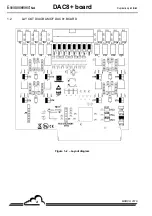
Page 210: ...EnvironnementS A DAC8 board Duplication prohibited MARCH 2018 4 1 2 LAYOUT DIAGRAM OF DAC8 BOARD Figure 1 2 Layout diagram...

Page 211: ...ICES ST9 ST10 ST11 ST12 ST13 ST14 ST15 Board n 1 for BETA5M VOC71M and MIR9000LCD Board n 2 for SAM32 and MIR9000LCD DAC 1 to 8 P2 P4 P6 P8 P10 P12 P14 P16 P1 P3 P5 P7 P9 P11 P13 P15 MODE SW1 to SW8 S...

Page 212: ...EnvironnementS A DAC8 board Duplication prohibited MARCH 2018 6 Page intentionally left blank...


Reviews: