background image

Environnement 

S.A


MP101M


Duplication prohibited 


SEPTEMBER 2013

1–22 


Figure 1–12 – Outline dimensions  


Summary of Contents for MP101M

Page 1: ...E MONITOR MP101M APRIL 2014 111 bd Robespierre 78300 POISSY TEL 33 0 1 39 22 38 00 FAX 33 0 1 39 65 38 08 http www environnement sa com GENERAL CHARACTERISTICS PRINCIPLE OF OPERATION OPERATION PREVENT...

Page 2: ...airs made by a third party without the written agreement of the seller The buyer is required to check the equipment as soon as possible upon receipt and acceptance and no later than eight days followi...

Page 3: ...0 17 CHAPTER 1 GENERAL CHARACTERISTICS 1 1 GENERAL 1 3 1 2 CHARACTERISCS 1 13 CHAPTER 2 PRINCIPLE OF OPERATION 2 1 BETA GAUGE PRINCIPLE FIGURE 2 1 AND FIGURE 2 2 2 3 2 2 FLOW REGULATION PRINCIPLE 2 6...

Page 4: ...TIVE ACTIONS 5 4 5 2 MODULE BOARD OF MP101M 5 8 5 3 GENERAL CONNECTION DIAGRAM 5 9 CHAPTER 6 APPENDIX LIST OF FIGURES Table 3 1 DB25 Connections 3 3 Table 3 2 MUX signals Acceptable limits on channel...

Page 5: ...pling tube RST 1 18 Figure 1 10 Regulated sampling tube RST 1 19 Figure 1 11 Links between units 1 21 Figure 1 12 Outline dimensions 1 22 Figure 2 1 General functional diagram 2 2 Figure 2 2 Beta gaug...

Page 6: ...3 3 8 09 2013 3 9 09 2013 3 10 09 2013 3 11 09 2013 3 12 09 2013 3 13 09 2013 3 14 09 2013 3 15 09 2013 3 16 09 2013 3 17 09 2013 3 18 09 2013 3 19 09 2013 3 20 09 2013 3 21 09 2013 3 22 09 2013 3 23...

Page 7: ...ntS A 0 7 SEPTEMBER 2013 Page Date 4 25 09 2013 4 26 09 2013 4 27 09 2013 4 28 09 2013 5 1 09 2013 5 2 09 2013 5 3 09 2013 5 4 09 2013 5 5 09 2013 5 6 09 2013 5 7 09 2013 5 8 09 2013 5 9 09 2013 5 10...

Page 8: ...EnvironnementS A MP101M Duplication prohibited SEPTEMBER 2013 0 8 Page intentionally blank...

Page 9: ...PROTECTION IN THE COUNTRY IN WHICH IT IS TO BE USED RADIATION PROTECTION SPECIAL INSTRUCTIONS 0 1 WARNING Radioactive sources are regulated substances it means that their import export providing tran...

Page 10: ...ent and of the sealing of sources are also provided for in these regulations Each source must be delivered with a certificate from the manufacturer certifying the characteristics of the source especia...

Page 11: ...is placed on the front side of the upper block of the receiver 0 3 2 WARNING LABELS AND SAFETY DEVICES The source holder is a rotary system The Carbon 14 source can take two positions storage and emi...

Page 12: ...NES 0 3 3 A RADIOACTIVE SOURCE Radio element Carbon 14 Shape Sealed classified C34343 under ISO2919 standards Activity 1 6MBq 15 means 1 84MBq maximum Emission Type energy 0 160 MeV Period of the radi...

Page 13: ...ions of braking Not considered Dose rate measurement Contact naked source 350 Sv h Dose rate measurement 10cm naked source 9 Sv h Dose rate measurement in the plastic box 0 2 Sv h Dose rate measuremen...

Page 14: ...ontact with the window of measurement we can consider a dose rate of 0 1 Sv h To exceed the regulatory threshold of 50000 Sv per year the technician should leave his hands in contact with the window o...

Page 15: ...ence of the radioactive source of the associated risks and of the meaning of various signals 0 6 3 INTERVENTION ON SOURCE HOLDERS Any intervention on source holders should be made by the supplier or u...

Page 16: ...s indicated by the following label Figure 0 4 Signaling label NB The date mentioned is the date of source calibration IT IS FORBIDDEN TO OPEN THE SOURCE HOLDER IT IS FORBIDDEN TO SEPARATE THE SOURCE F...

Page 17: ...e technical checking of radioprotection in particular Monthly checks using for instance the Contamination Test described in the 4 3 10 sheet of chapter 4 of the technical manual of the analyzer Period...

Page 18: ...EnvironnementS A MP101M Duplication prohibited SEPTEMBER 2013 0 18 Page intentionally left blank...

Page 19: ...s Figure 1 11 1 21 1 2 4 4 Dimension and weight Figure 1 12 1 21 1 2 4 5 Handling and storage 1 21 1 2 5 CERTIFICATIONS 1 23 1 2 5 1 PM10 USEPA designation 1 23 1 2 5 2 PM2 5 USEPA designation 1 23 1...

Page 20: ...EnvironnementS A MP101M Duplication prohibited SEPTEMBER 2013 1 2 1 GENERAL CHARACTERISTICS Figure 1 1 MP101M presentation...

Page 21: ...defined volume of air on a glass fiber filter The filter is automatically unrolled between the Beta source and a Geiger M ller counter GM according to defined sequences The difference in the radiation...

Page 22: ...ide The following components are mounted on the door A main power supply I O switch for ON OFF control located at the top right corner a backlit liquid crystal display 16 lines x 40 columns 240 x 128...

Page 23: ...Duplication prohibited MP101M EnvironnementS A 1 5 SEPTEMBER 2013 Figure 1 3 Front face with the door closed...

Page 24: ...counter for measurements of beta particles Geiger M ller tube detector 8 located on the same axis downstream of the ribbon In measurement mode the source and G M counter always maintain the same rela...

Page 25: ...PTEMBER 2013 1 reference gauge 3 source holder 4 flexible channel 5 capstan 6 disengageable pinch roller 7 take up reel 8 Geiger M ller tube detector 9 pressure assembly 10 pay out reel Figure 1 4 Fro...

Page 26: ...pin connector for the serial link RS232 RS422 4 One 3 contact TUCHEL connector for 24 V CC supply of the sampling head heating 3 One external pump power supply connector 5 One 15 pin socket for link...

Page 27: ...ts refer to Figure 1 6 The axis of pay out reel 1 The axis of take up reel 2 One motor for paper moving on 3 One rotation motor of the source holder 4 One motor of the pressure plate 5 1 Axis of pay o...

Page 28: ...ed into three parts separated by two aluminium plates the flow regulation part 1 the collector and Beta gauge assembly at the front of the unit 2 the electronics part 3 composed of the module board 4...

Page 29: ...re drop observed on passage at the throttle in the fluid circuit is used to deduce the velocity of flow and the flow rate three pressure sensors upstream and downstream of the flat orifice P1 4 P2 2 a...

Page 30: ...as specified in the 40 CFR 50 appendix L paragraph 7 3 2 and 7 3 4 4 The cyclone type separator is identified as a BGI VSCCTM Very Sharp Cut Cyclone particle size separator specified as part of EPA de...

Page 31: ...ic Average Floating average Geiger M ller counting time Programmable from 10 to 200 s Scan periods 10 mn 1 4 1 2 1 2 3 4 6 12 24 48 hours Measurement cycles 1 2 3 4 6 12 24 48 72 96 hours Measurement...

Page 32: ...range on one cycle Duration of cycle in hours Minimum detectable concentration in g m3 on one cycle 1 m3 h flow rate 6 12 24 2 1 0 5 Sampling rate 1 m3 h Spot area 2 4 cm2 Step between two spots 23 mm...

Page 33: ...300 VA Operating temperature 10 C to 40 C Alarm checks Permanent Detection and indication of malfunctions temperature pressure flow rates electric parameters Tests and diagnostics for maintenance Sele...

Page 34: ...p unit 4 fans upper part 1 tangential fan lower part 1 differential circuit breaker with 5 electrical distribution connectors 1 power supply terminal board with fuse holder 1 connection terminal board...

Page 35: ...range 0 to 30 C associated to a safety switch cut out at 60 C 1 2 4 2 Installation a Installation outdoors a 1 Concrete base For outdoor installation of the sealed box a concrete slab 2 m x 1 m is req...

Page 36: ...ampling head Sampling head channel MPM101M flexible channel Gasket compressed Gasket of tightness head MP101M link Do not crush MP101M channel with head The channel should remain flexible to enable di...

Page 37: ...1 10 Regulated sampling tube RST Fasten the meterological sensors on the external part of the sampling tube and connect the head heating to the socket marked tube heating on the rear panel Connect th...

Page 38: ...st enable to use the two flanges and the tightness gasket provided with the head The head must be able to slide in order to match up with no difficulty with the sampling conduit of the MP101M see Figu...

Page 39: ...11 Links between units 1 2 4 4 Dimension and weight Figure 1 12 The monitor comes in the form of a standard 19 inch 6 unit rack Length 360 5 mm Width 483 mm Height 266 mm Weight 16 kg external pump 1...

Page 40: ...EnvironnementS A MP101M Duplication prohibited SEPTEMBER 2013 1 22 Figure 1 12 Outline dimensions...

Page 41: ...uired 3 Use of the following configuration Parameter Value Paragraph of the manual Concentration unit g m3 3 3 4 4 Flow unit l min 3 3 4 4 Cycle timing 24 h 3 3 4 2 Period timing 1 h 3 3 4 2 Counting...

Page 42: ...of particles MP101M model is certified EN12341 when it operates under the following conditions 1 Use of a sampling head equipped with a fractionation screening device equivalent to the EN12341 and wi...

Page 43: ...ULATION PRINCIPLE 2 6 2 3 ACQUISITION AND PROCESSING OF MEASUREMENT PARAMETERS 2 8 2 4 ORGANIZATION OF MEASUREMENTS 2 8 2 5 REGULATED SAMPLING TUBE RST 2 11 Figure 2 1 General functional diagram 2 2 F...

Page 44: ...MP101M Duplication prohibited SEPTEMBER 2013 2 2 2 PRINCIPLE OF OPERATION Sampling head Sample tube Filter Vacuum pump Flow regulation device Emiter unit Receiver unit Beta gauge Figure 2 1 General fu...

Page 45: ...is aligned with the dust deposit and the counter G M The low energy Beta rays are absorbed by the matter by collision with the electrons whose number will be proportional to the density The matter co...

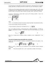
Page 46: ...the formula N N 1 N 1 1 1 The density of the air m1 contained in the volume V between the source and the detector is deduced from the temperature of the air knife T1 measured at the start of the cycl...

Page 47: ...relations a and b this gives N N e 1 2 k m m2 m1 and m m m 1 k Ln 2 1 N N 1 2 which gives the final relation m 1 k Ln m m 1 2 N N 1 2 where k 1 depends on the nature of the radiation emitted by the s...

Page 48: ...ol Motor External pump P1 P2 MP101M Fluid flow direction Figure 2 3 Flow regulation diagram P1 and P2 designate the absolute static pressures measured on both sides of the diaphragm through two axial...

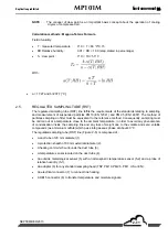
Page 49: ...etween the pressures measured upstream and downstream the orifice S1 and S2 are the surfaces of the two orifice sections is the air density at P1 pressure and T1 temperature with 1 0 0 1 0 T T P P As...

Page 50: ...e duration is selected to obtain maximum density of dust deposited on the filter this depends on the utilization site b Periodic This type of measurement is less precise than a cyclic measurement The...

Page 51: ...by the beta gauge Its integration duration and its calculation step are programmable Example of a running average for 24 hours and whose time step is 1h every hour the system calculates the average of...

Page 52: ...ity The dew point of air is the temperature to which the partial pressure of vapour is equal to its pressure of saturated vapour If the humid air is gradually cooled the dew temperature corresponds to...

Page 53: ...the reference method Consequently sampling must be carried out at a temperature close to the ambient temperature in order to avoid any phenomenon of condensation inside the sampling line and any loss...

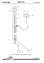
Page 54: ...EnvironnementS A MP101M Duplication prohibited SEPTEMBER 2013 2 12 Figure 2 5 Regulated sampling tube RST line assembly...

Page 55: ...ing is carried out at atmospheric temperature A continuous measurement of external relative humidity is carried out When the RH value exceeds the empirical threshold of 60 the line is heated and contr...

Page 56: ...EnvironnementS A MP101M Duplication prohibited SEPTEMBER 2013 2 14 This page is intentionally left blank...

Page 57: ...MENT Average 3 13 3 3 2 3 MEASUREMENT Synoptic 3 14 3 3 2 4 MEASUREMENT Graphic 3 16 3 3 2 5 MEASUREMENT Alarm display 3 17 3 3 2 6 MEASUREMENT Current cycle 3 18 3 3 3 CALIBRATION 3 19 3 3 3 1 CALIBR...

Page 58: ...1 USB FLASH DRIVE Flash drive information 3 63 3 3 8 2 USB FLASH DRIVE Backup data 3 64 3 3 8 3 USB FLASH DRIVE Erase flash drive data 3 65 3 3 8 4 USB FLASH DRIVE System restoration 3 65 3 3 8 5 USB...

Page 59: ...CC 4 ANALOG OUTPUT 4 20 ANALOG OUTPUT GROUND 5 ANALOG INPUT 1 21 ANALOG OUTPUT GROUND 6 ANALOG INPUT 2 22 ANALOG OUTPUT GROUND 7 ANALOG INPUT 3 23 ANALOG OUTPUT GROUND 8 ANALOG INPUT 4 24 ANALOG INPUT...

Page 60: ...3 of chapter 1 titled as Installing the regulated sampling tube RST Connect the cord of sampling head heating 3 and the supply cable of the meterological sensors 6 Connect the electrical mains power s...

Page 61: ...of time without any keyboard action duration is programmable in the Configuration Measurement mode menu the screen enters stand by mode Pressing any key makes the screen return to display mode 2 Carr...

Page 62: ...r calibration procedure details 6 Configure the measurement mode and the measurement channels in the CONFIGURATION menu Measurement mode advised 2h periods and 24h cycles 200 s counting duration Measu...

Page 63: ...ters are symbolized in white on black background 3 2 1 1 Screen areas definition Information area it displays the date and time in the top left corner In the top right corner the ALARM message is disp...

Page 64: ...the digit whose modification is in progress and Used to display the next page When there are several parameters pressing down allows displaying the next parameters 3 2 2 PROGRAMMING THE OPERATING PARA...

Page 65: ...ptic Alarm display Beta gauge Linearizations Date time Language Measurement mode Offsets Units Conversions Communications Factory settings Tabular Histogram RESET MUX signals Gauge test ARM7 Inputs Ou...

Page 66: ...s I 2 C Selection of the next item M e a s u r e m e n t C a l i b r a t i o n C o n f i g u r a t i o n S t o r e d d a t a T e s t s I 2 C c a r d s Selection of the next item D a t e T i m e L a n...

Page 67: ...nvironnementS A 3 11 SEPTEMBER 2013 3 3 2 MEASUREMENT This screen enables the user to select the measurement display mode instantaneous average synoptic or graphic to display the alarms and to check t...

Page 68: ...displayed on two display pages see the CONFIGURATION Measurement channels display Periodic concentration Cyclic concentration Average concentration Floating average Definition of keys specific to this...

Page 69: ...MEASUREMENT Average This screen displays the averages of the instantaneous values of the programmed measurement parameters Definition of keys specific to this screen For this screen the Start Stop an...

Page 70: ...CONFIGURATION Measure channels menu 2 date and hour 3 sample air inlet 4 source holder assembly 5 radioactive source diagrammed into this position the source is said out of gear it means that the ana...

Page 71: ...ountdown for the current blank the supply voltage of the Geiger counter the counting stated in count per seconds cp s 9 at the end of the Blank counting the source holder cylinder is placed again into...

Page 72: ...phs The validation to ON of the measurement channel field causes the plot display of the corresponding measurement values according to the parameters previously defined in the screen shown below This...

Page 73: ...alarm and its measurement unit The corrective actions to be carried out to cure these faults are given at Chapter 5 Pressing down the Hist key enables the user to display the Alarms historic screen T...

Page 74: ...rent cycle starting End field indicates the date and hour of the pump stop and the current cycle end Period field the number on the right side indicates the current period number with regard to the cy...

Page 75: ...P101M EnvironnementS A 3 19 SEPTEMBER 2013 3 3 3 CALIBRATION This menu is used to access calibration of Beta gauge and sampling flow rate NOTE The Beta gauge sub menu is not displayed when the analyze...

Page 76: ...alibration value the date of the previous calibration In this screen it is possible to manually modify the K calibration coefficient for example after a calibration or a manual check using the and key...

Page 77: ...tep and the pressure plate is placed into high position against the filter paper Then the pump starts the device passes into the Drying paper phase with visualization of the drying time countdown Then...

Page 78: ...rogrammed in the Calibration number field Between each Blank the GM counter is switched off When the 10 blanks are finished the screen displayed the average of the N blank measurements Then the cursor...

Page 79: ...cursor moves to the Pull out reference gauge field which blinks The new calibration K factor is displayed The user pulls out the reference gauge and validates by pressing down the F3 key Ending of Bet...

Page 80: ...d calibrations with the average of their respective measurement temperatures The K final or final span factor obtained at the end of the calibration and stored into memory In this screen pressing down...

Page 81: ...n below This screen displays The detail of measurements carried out on the reference gauge with the value of filter temperature for each measurement The average values of reference gauge counting and...

Page 82: ...rize the measurements of periodic cyclic and average concentration when using another analyzer as reference reference defined according to the standards EN12341 EN14907 or USEPA Parameters for the EPA...

Page 83: ...with the indicated method In this screen it is possible to manually modify the flow rate F coefficient for example after a calibration or a manual checking using the and keys select the F coefficient...

Page 84: ...ment is performed continuously Temperatures fields Filter field temperature at level filter Atm field External temperature measured by the meteo sensor if the meteo sensor option is available Flow rat...

Page 85: ...pump starts the device passes into Calibration phase the Reference flow rate preset is displayed as well as the measured Flow rate If the difference between both these values is higher than 1 5 l min...

Page 86: ...er then to validate this value with the key The instrument automatically modifies the flow rate F coefficient and displays the new flow rate value measured by the analyzer which is obtained with the n...

Page 87: ...is possible to manually control the opening and closing of the motor driven valve in order to calibrate the flow rate faster Press down the Manu key the 0 and keys are displayed screen shown below Co...

Page 88: ...alues of the three pressure sensors Upstream pressure Downstream pressure Atmospheric pressure Using a reference sensor barometric adjust the A and B values for the three sensors using the keys The pu...

Page 89: ...ent of alarm relays Serial link programming Reset of main programmable parameters 3 3 4 1 CONFIGURATION Date Time Language This screen is used to set the internal clock of the analyzer as well as to c...

Page 90: ...1 hour The sampling flow rate of the sampled air adjustable from 0 5 to 1 5 m3 h the standard value is 1 m3 h i e 16 67 l mn The counting time i e the duration of the radiation counting It is recomme...

Page 91: ...reen shown below The user has to press down the Start key in the MEASUREMENT menu screens Stop type fields manual hourly synchro the user inputs the Date and time field For the Cycle number field If i...

Page 92: ...the source is in sampling position Therefore it is necessary to go to one of the Instantaneous Average Synoptic screens of the MEASUREMENT menu to activate the measurement mode by pressing down the S...

Page 93: ...or each measure channel Channels number field allows the user to program the number of processed channels maximum 32 When more than eight parameters are programmed the and keys enable the user to go f...

Page 94: ...is value is added to the measurements value It is also used to program the measurement unit as for the conversion coefficients 3 3 4 5 CONFIGURATION Alarms Control Two thresholds per parameter are pro...

Page 95: ...ber of data bits can be 7 or 8 The second character is the parity control can be n for non e for even or o for odd The third character is the number of stop bits can be 1 or 2 Examples 8 n 1 8 data bi...

Page 96: ...n analyzer that uses an IP address of the shape 192 168 x x and the mask 255 255 0 0 This screen is used to configure the IP address and Mask of the analyzer HostName field name of the analyzer to be...

Page 97: ...ntified by a port number Two different ports can be bind to the analyzer Port A and Port B They are identified by two different corresponding port numbers 8003 and 8001 for example Port fields the num...

Page 98: ...ths years hours and minutes that memory can store data given the free space and data recording period Data can be edited in a table or histogram This screen allows programming of the date and hour edi...

Page 99: ...rement valid 01 Range 2 exceedence shooting 02 General alarm 20 Maintenance 40 Less than 2 3 of valid measurements during the average period 80 Power supply failure FF Configuration modification The d...

Page 100: ...e channel name the full scale with unit and the data recording period alternately blinking Definition of keys specific to this screen Return to previous menu Display previous stored data plot Display...

Page 101: ...us Parameters checking for maintenance operation Manual control of various elements Mother board control Arm7 board control NOTE In this screen the Gauge test and Mass test items are not displayed whe...

Page 102: ...T Filter temperature measured under the G M counter 100 mV 250 mV 400 mV 09 Int T Internal temperature of the analyzer measured on the mother board 100 mV 250 mV 400 mV 10 Up Pr Upstream pressure 3880...

Page 103: ...n order to show the DNP Arm7 activity when no LCD display is available SW1 indicates whether the analyzer is or is not in maintenance mode SW2 SW3 WS4 are not used SW5 shows whether WatchDog is active...

Page 104: ...tor Pump and Geiger counter controls 1 3 3 6 3 1 Motor for moving on filter ribbon To parameter the motor for moving on filter ribbon proceed in the order Using the keys go to the Filter field of scre...

Page 105: ...field and return to screen 1 press down the key 3 3 6 3 2 Motor of the source holder nozzle Using the keys go to the Nozzle field of the screen On the last line of screen 1 press down the Test key th...

Page 106: ...d below Moving up to start up the plate motor the plate moves up The motor stops after five seconds Press down the s key located below Moving down to start up the plate motor the plate moves down The...

Page 107: ...key located under Opening to start up the valve motor in Opening Check that the valve motor turns correctly towards the left user being placed in front of the valve Then press down the Pts key locate...

Page 108: ...is measurement series To do that it is necessary to follow the procedure described below Screen 1 1 This screen enables one to program the number of tests to be carried out on the same part of filter...

Page 109: ...order to dry the filter paper After what it carries out a blank measurement When the blank measurement is finished the analyzer carries out on the same part of filter paper the number of gauge tests...

Page 110: ...he number of measurement cycles done the countings duration the blank value of start the average obtained for the n countings the dust measurement and the standard deviation of this measurement stated...

Page 111: ...necessary to follow the procedure described below Screen 1 1 This screen enables one to program the number of tests to be carried out on the same part of filter and informs the user about the date th...

Page 112: ...Then it controls the pump switching on which will operate during 120 seconds in order to dry the filter paper After what it carries out a blank measurement When the blank measurement is finished the...

Page 113: ...ed The test can be stopped at any time by pressing down the Stop key in this case the analyzer displays the screen 3 of mass test start In this screen 3 press down the key to display the screen 2 and...

Page 114: ...EnvironnementS A MP101M Duplication prohibited SEPTEMBER 2013 3 58...

Page 115: ...13 3 3 7 I2C CARD S This menu enables the user to visualize the effective communications of various modules and to configure the various ESTEL RST and CPM boards 3 3 7 1 I2C CARD S Estel card s Refer...

Page 116: ...ight is the corresponding value stated in the standard measurement unit The Head heating field is used to test the heating control of the head To activate this control press down the key in order to s...

Page 117: ...Duplication prohibited MP101M EnvironnementS A 3 61 SEPTEMBER 2013 3 3 7 3 I2C CARD S CPM board This sub menu is available in the I2C Card s menu if the CPM option is available into the analyzer...

Page 118: ...tion of the analyzer and to carry out updates of the software The MP101MLCD is equipped with a USB socket located in the internal face of its panel door as indicated on the Figure 3 5 Figure 3 5 USB d...

Page 119: ...01M EnvironnementS A 3 63 SEPTEMBER 2013 3 3 8 1 USB FLASH DRIVE Flash drive information The USB FLASH DRIVE Flash drive information screen gives information about the storage capacity on the USB disk...

Page 120: ...SH DRIVE Backup data This function enables the user to copy backup onto the USB disk all data stored in the flash memory of the analyzer The user must confirm the backup by pressing down the key NOTE...

Page 121: ...The user has to confirm the erase of the USB disk content by pressing down the Yes key NOTE This operation does not assign the memory of the analyzer 3 3 8 4 USB FLASH DRIVE System restoration This f...

Page 122: ...aw the disk without respecting the withdraw procedure because of the risk of loosing data or resetting the analyzer In the USB FLASH DRIVE menu select the Withdraw sub menu using the and keys and pres...

Page 123: ...MAINTENANCE OPERATION SHEETS 4 3 4 4 EQUIPMENT NECESSARY FOR MAINTENANCE 4 27 Figure 4 1 Diagram of the Picolino pump 4 5 Figure 4 2 Diagram of the KNF pump 4 7 Figure 4 3 Cleaning of the sampling hea...

Page 124: ...it The manufacturer shall not be responsible for any adverse outcomes resulting from the following Use of the monitor by unqualified service personnel Use of the monitor under conditions other than t...

Page 125: ...F pump assembly 1 year 4 3 2 Sampling heads cleaning 1 month 4 3 3 Multiplexer MUX signals verification 3 months 4 3 4 Replacement of filter ribbon 1 to 3 years 4 3 5 Verification of pressure exerted...

Page 126: ...e the filtering cartridge 5 as well as an impeller 3 to check their wearing status 4 The filtering cartridges 5 must be cleaned according to the dust amount Purge the filter with compressed air from i...

Page 127: ...13 MAINTENANCE SHEET Monitor serial No OPERATION SHEET 4 3 1 Scope Check of Picolino pump assembly impellers pump PAGE 2 2 Periodicity 1 year Replacement parts Maintenance kit of PICOLINO VTE3 pump as...

Page 128: ...iaphragm F Check the cleanliness of the whole parts and if necessary clean them Replace the disc E and the lock washer L on the diaphragm and strongly tighten the whole using the screw D Replace the c...

Page 129: ...s Maintenance kit of KNF pump ref V02 K 0012 Dates A pump body B hexagon socket head screw C cylinder head D diaphragm screw E tightening disc F diaphragm G screw of body pump cover H pump body cover...

Page 130: ...arate the head from the sampling tube by simple vertical pulling Empty and clean the decantation bottle Brush the inlet grid Put down the head by simple vertical pulling a Pass a channel cleaning brus...

Page 131: ...Duplication prohibited MP101M EnvironnementS A 4 9 SEPTEMBER 2013...

Page 132: ...n prohibited SEPTEMBER 2013 4 10 MAINTENANCE SHEET Monitor serial No OPERATION SHEET 4 3 3 Scope Sampling heads cleaning PAGE 2 4 Periodicity 1 month Dates a b c Figure 4 3 Cleaning of the sampling he...

Page 133: ...EnvironnementS A 4 11 SEPTEMBER 2013 MAINTENANCE SHEET Monitor serial No OPERATION SHEET 4 3 3 Scope Sampling heads cleaning PAGE 3 4 Periodicity 1 month Dates a b c d e Figure 4 4 Cleaning of the US...

Page 134: ...uplication prohibited SEPTEMBER 2013 4 12 MAINTENANCE SHEET Monitor serial No OPERATION SHEET 4 3 3 Scope Sampling heads cleaning PAGE 4 4 Periodicity 1 month Dates a b c Figure 4 5 Cleaning of the US...

Page 135: ...odicity 30months Dates Procedure 1 Go to the TESTS MUX Signals screen 2 Compare the voltages values for each multiplexer inlet with the values written down in the control sheet provided with the analy...

Page 136: ...EnvironnementS A MP101M Duplication prohibited SEPTEMBER 2013 4 14 Page intentionally left blank...

Page 137: ...asurement in progress if necessary 2 Go to the TESTS Mother board Inputs Outputs screen and make the plate moves down 3 Open the door of the analyzer using the knurled button located on the left 4 Lif...

Page 138: ...ace the new reel on the pay out wheel in order to unroll the paper clockwise 8 Unroll the filter ribbon towards the right side above the two capstans and between the plate and the source block as show...

Page 139: ...t the counter of paper remaining capacity go to the CONFIGURATION Measurement mode screen and press down the key Using the key go to the Reel line on the ON OFF field and press down the key to modify...

Page 140: ...EnvironnementS A MP101M Duplication prohibited SEPTEMBER 2013 4 18 Page intentionally left blank...

Page 141: ...Open the door of the analyzer using the knurled button located on the left 4 Raise the disengageable pinch roller as shown in the just below picture 5 Insert a smooth paper between the filter ribbon a...

Page 142: ...p reel and or the pay out reel until the filter ribbon no longer moves Note that adjustment of the pay out reel pressure may be more important than that of the take up reel Example If the filter ribbo...

Page 143: ...e two measurements is lower than 1 5 L min carry out a flow rate calibration cf paragraph 3 3 3 2 Remark This test can also be carried out upstream the sampling line with the reference flow meter plac...

Page 144: ...ss between the sampling line and the analyzer inlet G12 VS 22 FPM and check the status of the gasket located under the retractable fitting of the MP101M sample inlet G06 027_0 2_0 V If necessary repla...

Page 145: ...Duplication prohibited MP101M EnvironnementS A 4 23 SEPTEMBER 2013...

Page 146: ...g flow rate PAGE 1 1 Periodicity 6 months Dates Procedure Refer to the paragraph 3 3 3 2 It is recommended to carry out a flow rate calibration During analyzer initial start up After replacement of th...

Page 147: ...icity 6 months Dates Procedure Refer to paragraph 3 3 3 1 It is recommended to carry out a Beta gauge calibration During analyzer initial start up After replacement of the filter paper ribbon After Ge...

Page 148: ...moves on The motor stops after seven seconds 4 Press down the key then go to Plate then press down the Test key then the s key under Moving up The plate moves up The motor stops after five seconds 5...

Page 149: ...dard deviation remains lower than 5 g cm If the test fails repeat the test no more than three times If the detector is too noisy it is probably necessary to replace it If the Blank average value fell...

Page 150: ...mos Temperature If relative humidity is higher than 60 check that Head temperature Atmos Temperature 5 C 3 If necessary adjust the A and B linearization coefficients of the three sensors 4 In case of...

Page 151: ...umidity sensor M04 0045 B SAV 1 GM detector equipped without GM tube M02 5055 A 1 GEIGER MULLER tube M02 72412 LND 1 Paper roll RF100 ref 10 370 392 M04 370 392 1 Board of RoHS absolute pressure senso...

Page 152: ...2412 LND 1 MP101 reference gauge M04 0004 B SAV 1 Upper sampling channel F09 5003 B SAV 1 Wired motor for valve source pressure assembly V01 0014 B 1 Temperature sensor of MP101M wired source D01 1164...

Page 153: ...M04 370 392 4 Maintenance kit for KNF PUMP V02 0012 A V02 K 0012 A 1 Gasket V RING FPM type VS G12 VS 22 FPM 2 Designation Reference Quantity Maintenance kit for 1 year Picolino pump MP101M K3 SAV Thi...

Page 154: ...EnvironnementS A MP101M Duplication prohibited SEPTEMBER 2013 4 32 Page intentionally left blank...

Page 155: ...TEMBER 2013 CHAPTER 5 CORRECTIVE MAINTENANCE 5 1 LIST OF FAULTS AND CORRECTIVE ACTIONS 5 4 5 2 MODULE BOARD OF MP101M 5 8 5 3 GENERAL CONNECTION DIAGRAM 5 9 Table 5 1 List of faults and correctives ac...

Page 156: ...EnvironnementS A MP101M Duplication prohibited SEPTEMBER 2013 5 2 Page intentionally left blank...

Page 157: ...e information provided in this document The monitor automatically and continuously self tests its main components Any malfunction detected is indicated by a plain language message on the display and a...

Page 158: ...er between the Pt16 ground test point and the Pt14 15V test point check the measured value Temperature At least one of the internal T C temperature or filter T C temperature exceeds the acceptable int...

Page 159: ...he valve motor control refer to the screen TESTS Mother board Inlets outlets Check the valve motor Check the valve Check the fluid circuit Flow rate The flow rate exceeds the allowed interval centered...

Page 160: ...ribbon Go to the CONFIGURATION Measurement Mode screen and reset the spots counter RST alarm RST link not detected Value of temperature or relative humidity is out of tolerances Check the RST line co...

Page 161: ...Duplication prohibited MP101M EnvironnementS A 5 7 SEPTEMBER 2013 Page intentionally left blank...

Page 162: ...ER 2013 5 8 5 2 MODULE BOARD OF MP101M Table 5 2 Configuration of Module board Jumper mark Symbols Function Symbols Function SW1 RS323 RS422 SW2 RS232 RS422 SW3 RS232 RS422 SW4 HT Geiger reading ST2 6...

Page 163: ......

Page 164: ...EnvironnementS A MP101M Duplication prohibited SEPTEMBER 2013 5 10 Page intentionally left blank...

Page 165: ...Duplication prohibited MP101M EnvironnementS A SEPTEMBER 2013 6 1 6 APPENDICES Appendix 1 ESTEL BOARD Appendix 2 DNP ARM7 BOARD...

Page 166: ...EnvironnementS A MP101M Duplication prohibited SEPTEMBER 2013 6 2 Page intentionally left blank...

Page 167: ...ION OF 2M ANALYZERS June 2009 WARNING Information contained in this document is likely to be modified without notice The designer reserves the right to modify the equipment without revising this docum...

Page 168: ...STEL board 15 1 5 5 Unrivet the back plate of rear panel of analyzer 15 1 5 6 Install board inside analyzer 16 1 6 EXTERNAL CONNECTION OPTIONS 17 Figure 1 ESTEL board index A 5 Figure 2 ESTEL board in...

Page 169: ...analog independent peripherals in order for example to store and process several months of data The analyzer can work as an autonomous unit of analysis when equipped with an ESTEL board 1 2 TECHNICAL...

Page 170: ...og output 2 11 30 Relay contact 4 10 29 Relay contact 5 3 22 GND Analog output 3 9 28 Relay contact 6 4 23 GND Analog output 4 15 34 GNDI Remote control 1 5 24 GND Analog input 1 16 35 GNDI Remote con...

Page 171: ...election board N 2 ESTEL selection board N 3 ST1 ST2 ST8 ESTEL selection board N 4 0 V to ground default ST3 Floating 0 V 0 1 V idem for the 4 DAC 0 10 V idem for the 4 DAC 0 20 mA idem for the 4 DAC...

Page 172: ...o boards ESTEL selection if three boards ST5 ST6 ST7 ESTEL selection if four boards 0 V to ground default ST8 Floating 0 V DAC1 0 1 V or optional 2 5 V and 10 V idem for the four DAC DAC2 0 10 V idem...

Page 173: ...ured for 0 10 volts with adjustment of half gain In menu Tests ESTEL boards adjust the A and B coefficients of each channel in order to obtain 0 5 V at analog output for an analog to digital converter...

Page 174: ...one or two ESTEL boards and provides menus that let the user adjust and configure each board ESTEL board programming and configuration is carried out from the ESTEL card s menu of the Carte s I2C scr...

Page 175: ...t range the analyzer switches to the next higher range It switches back to the lower range when measurement again falls below 85 When the user assigns several measurement ranges to only one analog out...

Page 176: ...of these analog inputs Name fields are used to enter a name of up to eight alphanumeric characters Unit fields are used to select the unit from the toggle menu none ppt ppb ppm g m3 mg m3 gr m3 g Nm3...

Page 177: ...n chamber Zero Air On Zero relay is triggered Span On Span relay is triggered Zero Ref On Zero Ref relay is triggered Auto Span On Auto Span relay is triggered Warm up On Warm up relay is triggered St...

Page 178: ...CARD S Remote controls This screen displays the assignment of remote control inlets The available assignment choices are Inactive Stop mode Zero Ref Zero Span Auto span The Test column is used to dis...

Page 179: ...work of the analyzer Analyzer s safety recommendation Respect the connection of ESTEL board Module board at J20 when reassembling Use the steps illustrated below for installation or replacement of the...

Page 180: ...between ESTEL board and module board 5 Fixing screw of ESTEL board on rear panel of analyzer Disconnect connecting cable between ESTEL board 4 and module board 3 Unscrew fixing screws 5 of ESTEL board...

Page 181: ...d inside analyzer ANALYZER SWITCHED OFF 1 Vertically insert board inside its slot 2 Rescrew board on the slot 3 Replace connector on ESTEL board 4 Reconnect module board at J20 5 Replace cover on anal...

Page 182: ...External ESTEL connection one insulated output P10 1350 A Figure 4 Cable D02 INF 37 37M M A 1 Tie point block interface board C10 0012 A 2 Symmetrical DIN track limit stop G13 IB 18066 D03 103 002 26...

Page 183: ...Duplication prohibited ESTEL Board EnvironnementS A JUNE 2009 17 Figure 3 External connection option Figure 4 External connection option four insulated outputs...

Page 184: ...EnvironnementS A ESTEL Board Duplication prohibited JUNE 2009 18 Page intentionally left blank...

Page 185: ...LINUX OPERATING SYSTEM NOVEMBER 2009 WARNING Information contained in this document is likely to be modified without notice The designer reserves the right to modify the equipment without revising thi...

Page 186: ...cription for the DNP Arm7_V1 board 6 Table 3 Serial link configuration of the DNP Arm7_V1 board 7 Table 4 Inlet outlet descriptions for the DNP Arm7_V2 board 10 Table 5 Switch S1 description for the D...

Page 187: ...e The DNP Arm7 board enables dialog with the measurement module and assumes its inputs output functions display RS232 metrological calculations 1 2 TECHNICAL CHARACTERISTICS SAMSUNG Arm7 microprocesso...

Page 188: ...EnvironnementS A DNP ARM7 board Duplication prohibited NOVEMBER 2009 4 1 3 DNP ARM7 BOARD CONFIGURATION Upper guiding mark of the board Figure 1 DNP Arm7_V1 board...

Page 189: ...Board power supply JP2 Extension JP15 Life LED JP3 I2C bus JP16 ON OFF switch JP4 USB JP17 Module n 1 ON OFF JP5 Backlighting JP18 Module n 2 ON OFF JP6 LCD screen JP19 Module n 3 ON OFF JP7 six key k...

Page 190: ...ammed IP Address down position Inactive WatchDog S1 5 up position Active WatchDog down position Software start up in service mode address 192 168 0 30 S1 4 up position Application starting up down pos...

Page 191: ...009 7 Table 3 Serial link configuration of the DNP Arm7_V1 board Jumper marks Symbols Nature of operations By default up position COM2 TX towards RS4i JM1 down position COM2 TX towards module up posit...

Page 192: ...EnvironnementS A DNP ARM7 board Duplication prohibited NOVEMBER 2009 8 Page intentionally left blank...

Page 193: ...Duplication prohibited DNP ARM7 board EnvironnementS A NOVEMBER 2009 9 Upper guiding mark of the board Figure 2 DNP Arm7_V2 board...

Page 194: ...oard power supply JP2 Extension JP15 Life LED JP3 I2C bus JP16 ON OFF switch J1 USB JP17 Module n 1 ON OFF JP5 Backlighting JP18 Module n 2 ON OFF JP6 LCD screen JP19 Module n 3 ON OFF JP7 six key key...

Page 195: ...toStart IP Address 192 101 0 1 ST6 Programmed IP Address Inactive WatchDog ST5 Active WatchDog Software start up in service mode address 192 168 0 30 ST4 Application start up AutoLoad ON Update of pro...

Page 196: ...09 12 Table 6 Serial link configuration of the DNP Arm7_V2 board Jumper marks Symbols Nature of operations By default up position COM2 TX towards RS4i JM1 down position COM2 TX towards module up posit...

Reviews: