

SHOULD YOU ENCOUNTER ANY PROBLEMS INSTALLING THIS UNIT CALL
0345 27 27 810
23
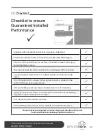
09
Maintenance
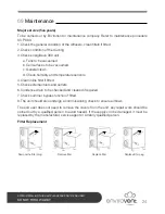
Recommended maintenance schedule
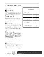
The following checks are recommended to ensure that this heat recovery system operates
at its optimum level.
Yearly checks
To be carried out by the user or maintenance company.
•
Check there is sufficient airflow coming through the diffusers.
•
Change filters x 2 (see illustrations on page 24)
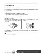
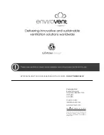
Clearing filter indication
• To clear the filter indication light press plus
(+) and minus (-) on the switch panel for
4 seconds.
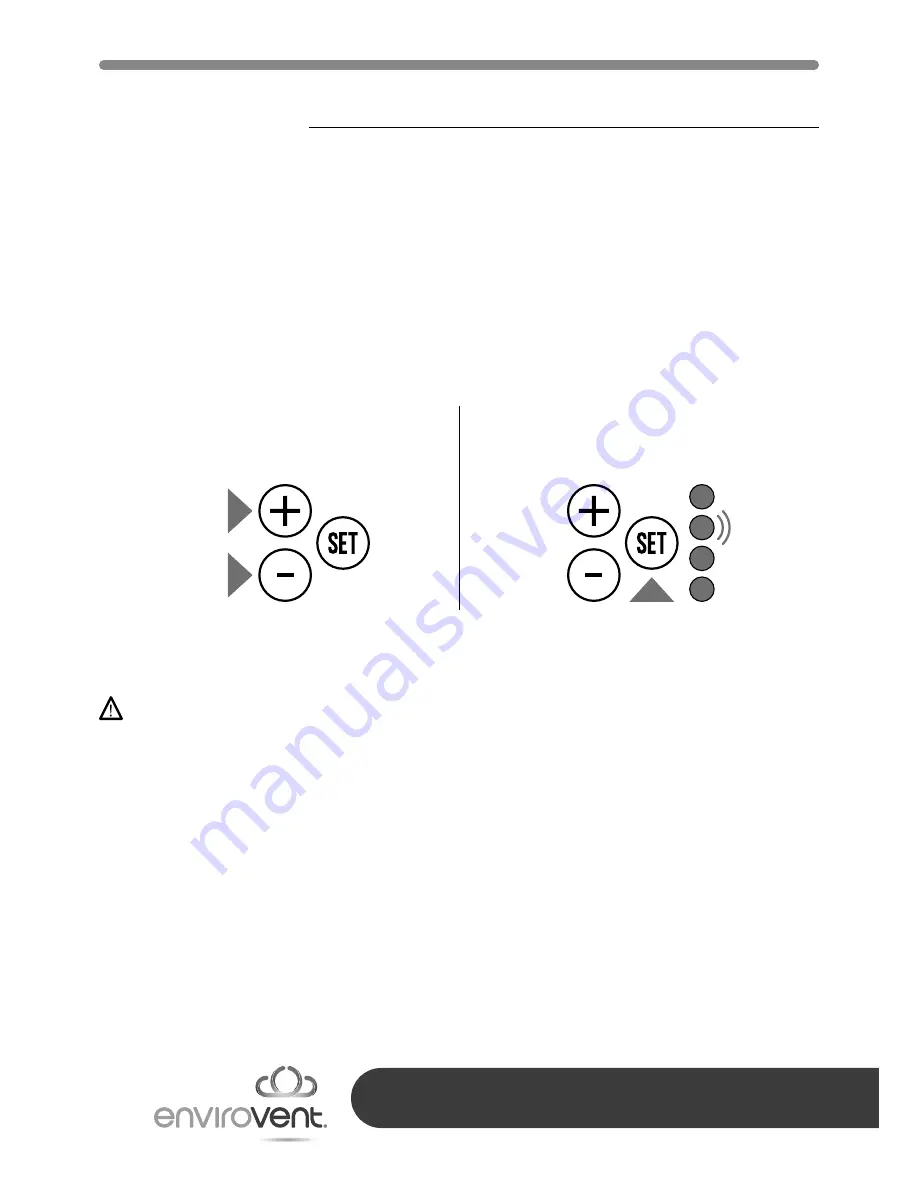
• When all the LEDs light up press SET for
1 second.
This will reset the filter counter and no more action is required. Filter indicator is set to 12
months as standard.
Filter maintenance is required for the proper function of the unit, not doing so may
invalidate the warranty.
1 sec
4 sec


