


D4K PRo® User Manual
D4K_UserManual_v1.3_EN.docx, 2021-02-12
Page 7 of 52
2
User Information
NOTICE
This User Manual has been created for
version 3.0
of
. If some information is not covered
in this Manual, please let us know by contacting
2.1
Functional Description
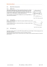
The D4K® printer builds 3D models by curing liquid photopolymers through a projector system.
During the build process, the model is built layer by layer. A mechanical system moves the build platform up so that the cured
material sticks to the build platform or to the previous layer.
Before starting the build process, certain calibration functions need to be carried out, which are performed at the factory.
The photopolymer is then directly poured into the material tray. The job is transferred to the printer through Envision One RP®
software or via USB drive. The build process can be started.
After the build process has finished, the built parts are removed from the build platform using a scalpel or scraper and treated
according to the corresponding cookbook.
2.2
Purpose of the Document
This instruction manual:
•
describes the working principle, operation and maintenance of the printer, and
•
provides important information on safe and efficient handling of the printer.
NOTICE
The operation of the Envision One RP Software is described in the
Envision One RP Software Manual
.
This document forms an elementary part of the system, includes important notes, tolerances for calibration tasks if applicable,
and must be paid close attention to both when starting up the printer and during the operation. Keep the hardware documentation
in close proximity of the printer, so that the operator can access it at all times.
2.3
Target Group
This instruction manual is intended for:
•
the customer (company operating the printer) whose responsible employees have been trained by the manufacturer or the
distributor,
•
trained operators for operation and
•
persons with specialist technical training (mechanics/electrical engineering) for troubleshooting/fault elimination and
maintenance.
2.4
Locations in the Instruction Manual
All the directions and locations in this instruction manual are always seen from the working position of the operator.
2.5
Typographic Conventions
This instruction manual uses different formatting elements and symbols. Their meaning is explained in this section.
Formatting Element
Example
Enumerations are indicated by a dot.
•
Safety gloves
•
Safety googles
Instructions with a defined order are numbered consecutively.
1. Loosen the screws.
2. Remove the build platform.
3. Clean the holding.
4. Install the build platform.
5. Tighten the screws.


