background image

21

NDS OUTDOOR SPLIT INSTALLATION MANUAL

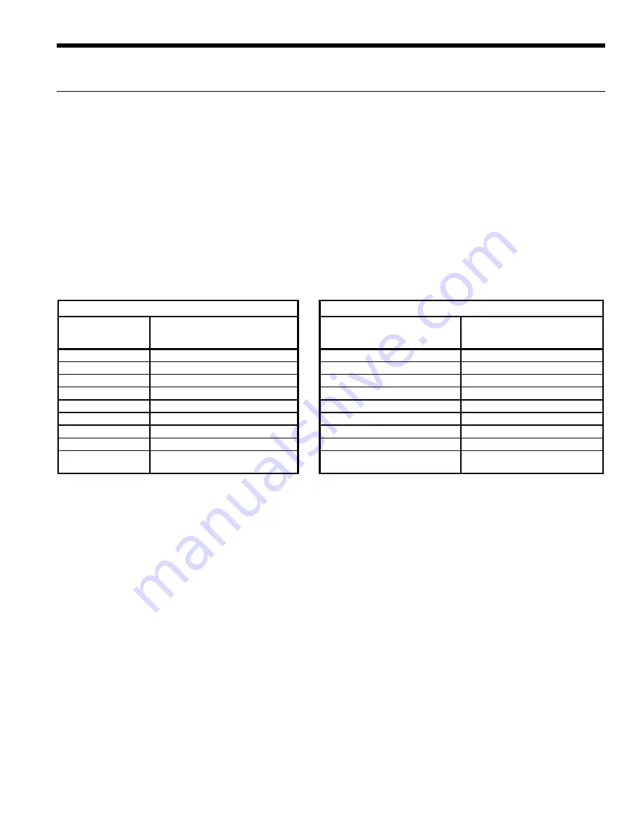
The following tables show the codes that will be displayed on the different ComforTalk and FaultFlash thermostats.

FaultFlash Thermostats

ComforTalk Thermostats

Thermostat Display

Lockout Code 

Thermostat Display

Lockout Code 

Lockout Description

Lockout Description

2 Flashes

High Pressure Fault

"High Pressure" or "E2"

High Pressure Fault

3 Flashes

Low Pressure Fault

"Low Pressure" or "E3"

Low Pressure Fault

4 Flashes

Not Applicable

"E4"

Not Applicable

5 Flashes

Water Flow Fault

"Water Flow" or "E5"

Water Flow Fault

6 Flashes

Not Applicable

"E6"

Not Applicable

7 Flashes

Condensate Fault

"Condensate" or "E7"

Condensate Fault

8 Flashes

Voltage out of Range

"Voltage Range" or "E8"

Voltage out of Range

9 Flashes

RPM Fault

"RPM" or "E9"

RPM Fault

10 Flashes

Comfort Alert Compressor

Module Fault

"Comfort Alert" or "E10"

Comfort Alert Compressor

Module Fault

Lockout code 10 - see Comfort Alert module to determine the specific flash code for

compressor abnormalities.

These thermostats can be configured to display the lockout condition "text" or error number.

* A slow flash of 1 second on and off means the heat pump microprocessor SW2-1 is configured

  for "Test Mode" or thermostat is miswired.
  Lockout code 10 - see Comfort Alert module to determine the specific flash code for

  compressor abnormalities.

TA32W02 and TP32W03 Thermostats

 TP32U03, TP32U04 and TP32U05 Thermostats

Thermostat Displays

Fault Flash

 When using a TA32W02 or TP32W03 thermostat and 
SW2-8 is in the pulsing “L” position, FaultFlash will enable 
a user to view the thermostat and count the fault indicator 
flashes to determine the lockout condition the unit is 
experiencing.

ComforTalk

When using a TP32U03, 04 or 05 thermostat and SW2-8 
is in the pulsing “L” position, ComforTalk will enable the 

Microprocessor Control cont.

user to view the thermostat and determine the fault. The 
thermostat can be configured to show either lockout text 
or lockout codes. 

The LED board on the front of the unit will display all 
lockouts. The Low Pressure LED will flash for a low pressure 
condition or a Comfort Alert fault. If the low pressure 
lockout was caused by Comfort Alert codes 4, 6 or 7, then 
the Comfort Alert will be flashing. If no Comfort Alert code 
is visible, then it is a low pressure lockout.

Summary of Contents for NDS026 Series

Page 1: ...stallation Information Water Piping Connections Electrical Data Startup Procedures Troubleshooting Preventive Maintenance NDS Installation Manual Geothermal Water Source Outdoor Split Heat Pump 2 to 6 Tons Dual Capacity ...

Page 2: ......

Page 3: ...efrigerant Coil Compatibility 13 Wiring Schematics 14 17 Microprocessor Control 18 21 Operation Logic Data 22 DIP Switch Settings 22 Refrigeration 23 24 Line Set Sizes 24 Pressure Temperature Conversion Chart for R 410A 25 Operating Parameters 26 Pressure Drop 27 Compressor and Thermistor Resistance 27 Refrigerant Circuit Guideline 28 Heat of Extraction Rejection Data 28 Reference Calculations 29 ...

Page 4: ...oor Split Unit Capacity 026 038 049 064 072 NOTE 026 049 uses the FC1 GL and 060 072 uses the FC2 GL the flow center is factory installed If these flow centers do not meet the flow requirements select A None for digit 10 Coax Options C Copper N Cupronickel Flow Center A None B Flow Center IntelliStart Options 0 No IntelliStart 3 IntelliStart Voltage 1 208 230 60 1 Vintage A Current ...

Page 5: ...ng and air conditioning equipment Condensate Drain Follow the blower coil manufacturer s instructions Duct System All blower coil units air coils must be installed as specified by the manufacturer s installation instructions however the following recommendations should considered to minimize noise and service problems An air filter must always be installed upstream of the air coil on the return ai...

Page 6: ...line sets should be insulated with a minimum of 1 2 closed cell insulation All exterior insulation should be painted with UV resistant paint or covering to ensure long insulation life Air Handler Installation Air handlers used with dual capacity units must be capable of operating with a minimum of 2 blower speeds Refer to the manufacturer s instructions for the blower coil unit for details on inst...

Page 7: ...nace illustration for typical Dual Fuel application Thermostat Wire From Furnace Wire T o Thermostat Up Flow Fossil Fuel Furnace Condensate Drain must be trapped A or Slab Coil Supply Duct Insulated Suction Line Return Duct Lineset T o Air Handler Disconnect Typical Split System Heat Pump Coil Add on Fossil Fuel Furnace In add on Envision Split applications the coil should be located in the supply...

Page 8: ...s e L m p p 2 n a h t s s e L m p p 2 n a h t s s e L a i n o m m A Corrosion m p p 5 n a h t s s e L m p p 5 n a h t s s e L m p p 5 n a h t s s e L e d i r o l h C a i n o m m A m p p 5 n a h t s s e L m p p 5 n a h t s s e L m p p 5 n a h t s s e L e t a r t i N a i n o m m A m p p 5 n a h t s s e L m p p 5 n a h t s s e L m p p 5 n a h t s s e L e d i x o r d y H a i n o m m A m p p 5 n a h t ...

Page 9: ...trench settling All 1 1 4 inch piping should be insulated with a minimum of 1 2 inch closed cell insulation from below the ground surface to the loop circulator IMPORTANT A freeze detection thermostat is installed in the unit to automatically start loop circulator pump if loop temperature drops below 20 F Loop freeze detection should also be maintained to the lowest temperature the insulated loop ...

Page 10: ...at Relay or use TP32U03 or TP32U04 General Be sure the available power is the same voltage and phase as that shown on the unit serial plate Line and low voltage wiring must be done in accordance with local codes or the National Electric Code whichever is applicable See unit electrical data for fuse or cicuit breaker sizing information Electrical Data Model Rated Voltage Voltage Min Max Compressor ...

Page 11: ...onnections drawings Physical Data All units have TXV expansion devices and 1 2 in 12 2 mm and 3 4 in 19 1 mm electrical knockouts Brass service valves are sweat type valves Model 026 038 049 064 072 Compressor 1 each Dual Capacity Scroll Factory Charge R 410A oz kg 52 1 47 56 1 59 90 2 55 92 2 61 104 2 95 Coax and Water Piping Water Connections Size Swivel in mm GeoLink Swivel Connectors Brass Ser...

Page 12: ... 042 060 only A Current 20 20 kW available on 060 only NOTE Kit NAHBC must be ordered to field convert the NAH042 060 to bottomflow air discharge 1 3 4 6 7 8 9 10 11 12 Air Handler Indoor Split Model Single Indoor Split Model Dual Capacity Outdoor Split Model Dual Capacity Airflow CFM Electric Heat kW NAH022A 1R NSZ022 800 5 NAH026A 1R NDZ026 NDS026 925 5 NAH030A 1R NSZ030 980 5 10 NAH036A 1R NSZ0...

Page 13: ... 3 11 08 220 99 79 200 90 71 208 230 1ph ECM variable speed 1 2 373 1 746 20 x 24 508 x 635 3 4 19 05 11 x 10 279 x 254 Air Handler Model Number Hydronic Hydronic Coil 3 7 8 22 22 13 7 8 22 22 6 94 0 64 3 8 9 52 Air Handler Model Number Refrigerant Evaporator Coil 5 83 0 54 3 8 9 52 2 3 12 5 8 15 87 7 8 22 22 3 8 9 52 Refrigerant R 410a 3 4 19 05 11 x 10 279 x 254 ECM variable speed 1 2 373 1 746 ...

Page 14: ...ressure Low Pressure Comfort Alert Not Used Not Used Not Used Not Used Current Fault Status 6Off 7On Y1 Y2 O Not Used Not Used SL1 SL2 Inputs 6 On 7 Off Lo Capacity Compressor RV FAN Not Used Loop Pump1 Outputs 6 Off 7 Off Not Used Outputs2 Diagnostic Modes GreenLED not flashing Hi Capacity Compressor Loop Pump2 Not Used Not Used Not Used Not Used Not Used Not Used Not Used Not Used Not Used Tan O...

Page 15: ...D HP LP RV SW1 SW2 SW3 Compressor Contactor Loop Pump Relay1 Fuses Freeze Detection sensor High Pressure Switch Low Pressure Switch Reversing Valve Coil Not Used DIP Package 8 Position DIP Package 5 Position Relay Contacts N O N C G T 1 3 2 P L1 Loop Pump Relay2 Not Used CS Compressor Solenoid Not Used Legend 1 Connection of remote unit that does not have a loop pump for slave operation 2 24V Acce...

Page 16: ...off LED Normal Display Mode 1 Off 6 On 7 On Not Used FD thermistor loop 15 F well 30 F High Pressure Low Pressure Comfort Alert Not Used Not Used Not Used Not Used Current Fault Status 6 Off 7 On Y1 Y2 O Not Used Not Used SL1 SL2 Inputs 6 On 7 Off Lo Capacity Compressor RV FAN Not Used Loop Pump1 Outputs 6 Off 7 Off Not Used Outputs2 Diagnostic Modes GreenLED not flashing Hi Capacity Compressor Lo...

Page 17: ...d Fuse CC CR1 CR2 CR3 CR4 F1 and F2 FP HP LP RV SW1 SW2 SW3 Compressor Contactor Loop Pump Relay1 Fuses Freeze Detection sensor High Pressure Switch Low Pressure Switch Reversing Valve Coil Not Used DIP Package 8 Position DIP Package 5 Position Relay Contacts N O N C G T 1 3 2 P L1 Loop Pump Relay2 Not Used CS Compressor Solenoid Not Used Legend Crankcase Heater CA Comfort Alert 1 Connection of re...

Page 18: ...rd diagnosis Refer to the Field Selection DIP Switch SW2 1 table Microprocessor Control Heating Operation Heat 1st Stage Y1 The blower motor is started on low speed immediately PSC ON the loop pump is energized 5 seconds after the Y1 input is received and the compressor is energized on low capacity 10 seconds after the Y1 input The blower is switched to medium speed 15 seconds after Y1 input ECM o...

Page 19: ...y outputs are de energized The blower will continue to run on low speed If the thermostat calls for heating emergency heat operation will occur Comfort Alert lockouts cannot be reset at the thermostat All other lockout modes can be reset at the thermostat after turning the unit off then on which restores normal operation but keeps the unit lockout LED illuminated Interruption of power to the unit ...

Page 20: ...mber LED Description Automatic Reset of Alert Codes Flash Code 1 Long Run Time Not applicable Flash Code 2 System Pressure Trip Not applicable Flash Code 3 Short Cycling Four alert free on and off cycles to reset automatically Flash Code 4 Locked Rotor Four alert free on and off cycles to reset automatically Flash Code 5 Open Circuit One alert free on and off cycles to reset automatically Flash Co...

Page 21: ...the lockout condition text or error number A slow flash of 1 second on and off means the heat pump microprocessor SW2 1 is configured for Test Mode or thermostat is miswired Lockout code 10 see Comfort Alert module to determine the specific flash code for compressor abnormalities TA32W02 and TP32W03 Thermostats TP32U03 TP32U04 and TP32U05 Thermostats Thermostat Displays Fault Flash When using a TA...

Page 22: ...Blower Comp 4 NOT USED N A N A 5 NOT USED N A N A 6 Input Diagnostics Allows viewing the inputs from the thermostat to the control board such as Y1 Y2 O G W SL1 In on the LED display Diagnostic Inputs viewed at LEDs Normal Display viewed at LEDs 7 Output Diagnostics Allows viewing the outputs from the control board such as the compressor reversing valve blower and loop pump on the LED display Diag...

Page 23: ...l refrigerant to be added 20 ft x 0 5 oz 10 oz Solution 10 oz should be added to the recommended charge of 86 oz found in the Charge Amount with NAH Air Handler column for a total charge of 96 oz Refrigeration After initial charge the system should be operated and the system subcooling and superheat verified to the Unit Operating Parameters table If an air handler manufactured by others is used th...

Page 24: ...he difference will be the subcooling value for that unit Refer to the Operating Parameters tables for subcooling ranges at specific enter water conditions Line Set Sizes Unit Size Air Handler 20 feet 40 feet 60 feet Factory Charge oz Charge Amount with NAH Air Handler oz Suction Liquid Suction Liquid Suction Liquid 026 NAH026 5 8 OD 3 8 OD 3 4 OD 3 8 OD 3 4 OD 1 2 OD 52 74 038 NAH036 3 4 OD 3 8 OD...

Page 25: ...466 128 5 586 146 5 108 35 4 228 78 1 348 106 7 468 128 8 588 146 8 110 36 4 230 78 7 350 107 2 470 129 1 590 147 1 112 37 3 232 79 2 352 107 6 472 129 4 592 147 3 114 38 2 234 79 8 354 108 0 474 129 8 594 147 6 116 39 1 236 80 3 356 108 4 476 130 1 596 147 9 118 40 0 238 80 9 358 108 8 478 130 4 598 148 2 120 40 9 240 81 4 360 109 2 480 130 7 600 148 4 122 41 7 242 81 9 362 109 6 482 131 1 602 14...

Page 26: ...24 39 3 0 145 160 330 360 140 160 375 425 7 17 7 15 4 10 24 39 Second Stage Operation Cooling No Desuperheater Entering Water Temp F Water Flow GPM Ton NDS026 thru NDS064 NDS072 NDS026 thru NDS072 Suction Pressure PSIG Discharge Pressure PSIG Suction Pressure PSIG Discharge Pressure PSIG Superheat Subcooling Water Temp Rise F Air Temp Drop F DB 50 1 5 120 140 200 245 105 150 210 270 7 17 6 14 15 2...

Page 27: ... 1 6 1 4 1 3 12 3 8 3 5 3 3 3 0 2 8 16 6 5 6 0 5 6 5 2 4 8 20 9 7 9 1 8 5 8 0 7 4 064 part load 6 1 0 0 9 0 9 0 8 0 8 10 2 6 2 5 2 3 2 1 2 0 14 5 0 4 7 4 4 4 1 3 8 18 8 1 7 6 7 1 6 6 6 1 072 full load 12 3 2 3 0 2 8 2 6 2 4 15 4 5 4 2 4 0 3 7 3 4 18 6 0 5 7 5 3 4 9 4 6 21 7 8 7 3 6 8 6 4 5 9 072 part load 10 2 3 2 1 2 0 1 9 1 7 13 3 6 3 3 3 0 2 8 2 6 16 5 0 4 6 4 3 4 0 3 7 19 6 5 6 2 5 8 5 4 5 0 5...

Page 28: ...e difference delta T across filter drier 7 6 10 Refrigerant Circuit Guideline Heat of Extraction Rejection Data Model GPM Heat of Extraction kBtuh Heat of Rejection kBtuh 30 F 50 F 70 F 90 F 30 F 50 F 70 F 90 F 110 F 026 Part Load 3 0 13 1 17 6 21 5 23 5 22 9 21 8 5 0 9 4 13 8 18 6 22 6 21 7 23 6 23 0 21 7 20 2 7 0 9 6 14 1 18 9 23 0 21 9 23 7 23 1 21 7 20 2 Full Load 4 0 17 8 23 4 28 5 31 0 31 2 ...

Page 29: ... LAT leaving air temperature F TH total heating capacity MBTUH LC latent cooling capacity MBTUH S T sensible to total cooling ratio Operating Limits Cooling Heating Air Limits Minimum ambient air DB 10 F 23 3 C 10 F 23 3 C Rated ambient air DB 80 0 26 7 C 70 F 21 1 C Maximum ambient air DB 120 48 8 C 85 F 29 C Water Limits Minimum entering water 30 F 1 C 20 F 6 7 C Normal entering water 50 110 F 1...

Page 30: ...eck The Following 8 Decrease the cooling set point several degrees and verify high speed blower operation 9 Adjust the cooling setpoint above the room temperature and verify that the compressor and water valve or loop pumps deactivate 10 Initiate a control signal to place the unit in the heating mode Heating set point must be set above room temperature 11 First stage heating will energize after a ...

Page 31: ...easure suction temperature here at TXV bulb in cooling modes Cooling Cycle Analysis COOLING TXV ACTIVE RIGHT TO LEFT ClgTXV Measure liquid line temperature and pressure here in both heating and cooling modes COAX HEATING TXV ACTIVE LEFT TO RIGHT HtgTXV Measure suction temperature here at TXV bulb in heating modes Suct PSI ____ Suct sat temp ____ Volts ____ Amps ____ EWT ____ LWT ____ Suct temp ___...

Page 32: ... SW2 1 NA SW2 6 On SW2 6 On SW2 6 Off SW2 6 On SW2 6 Off SW2 7 On SW2 7 On SW2 7 On SW2 7 Off SW2 7 Off Drain Drain Pan Overflow Lockout Drain Pan Overflow Y1 Compressor On or Low Blower Low Water Flow FD Thermistor Loop 15 F Well 30 F Lockout FD Thermistor Loop 15 F Well 30 F Y2 Compressor On or High Blower Medium High Pressure High Pressure 600 PSI Lockout High Pressure 600 O Reversing Valve Blo...

Page 33: ... when necessary Units should never be operated without a filter Obtaining Parts When ordering service or replacement parts refer to the model number and serial number of the unit as stamped on the serial plate attached to the unit If replacement parts are required mention the date of installation of the unit and the date of failure along with an explanation of the malfunctions and a description of...

Page 34: ...Coax 62I504B01 62I542B01 62I543B01 TXV 33P609 01 33P609 03 33P609 05 33P609 06 Reversing Valve 33P506 04 33P503 05 33P526 04 Filter Dryer 36P500B01 36P500B02 Electrical Comfort Alert 19P571 02 Contactor 13P004A03 Transformer 15P501B01 3 Pole Power Block 12P503 06 2 Pole Screw Term Block 12P500A01 Status Light Board 17P503 02 Harness Status Light Board 11P783 01 Premier Board 17P513 07 Sensors Safe...

Page 35: ......

Page 36: ... Inc 9000 Conservation Way Fort Wayne IN 46809 9794 WaterFurnace has a policy of continual product research and development and reserves the right to change design and specifications without notice Product Envision NDS Type Geothermal Water Source Outdoor Split Heat Pump Size 2 6 Tons Dual Capacity Document Installation Manual IM1004SN 03 11 ...

Reviews: