34
NSKW INSTALLATION MANUAL
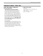
Freeze Detection
The freeze detection sensor will monitor the liquid
refrigerant temperature entering the water coil in the
heating mode. If the temperature drops below the freeze
detection trip point for the recognition delay period, the
condition will be recognized as a fault. The freeze detection
trip point will be factory set for -1.1°C and will be field
selectable for -9.4°C by removing a jumper wire on BI-4
for the source and BI-5 for the load. The freeze detection
fault condition will be bypassed for 2 minutes at normal
compressor startup to allow the refrigeration circuit to
stabilize. If the freeze detection sensor becomes unreliable
at any time compressor operation will immediately be
suspended until the problem is corrected. This will be
displayed as an alarm on the BAS and the MUI. This alarm
will be reported as “Water Low Temp Limit”.
High Pressure
The high-pressure switch shall be a normally closed (NC)
switch that monitors the systems refrigerant pressure. If
the input senses the high-pressure switch is open it must
disable the compressor output immediately and count the
fault. The compressor minimum on time does not apply if
the high-pressure switch opens. The compressor will not
restart until the compressor short cycle time delay has
been satisfied.
Low Pressure
The low-pressure switch shall be a normally closed (NC)
switch that monitors the systems refrigerant pressure.
The input shall be checked 5 seconds before compressor
start up and then ignored for the first 2 minutes after the
compressor output (BO-2) is enabled. If the switch is open
continuously for 30 seconds during compressor operation
the compressor output (BO-2) will be disabled. The
compressor will not restart until the compressor short cycle
time delay has been satisfied.
Alarm Outputs
The alarm output will be enabled when the control is in
the lockout mode and will be disabled when the lockout is
reset.
Test Mode
By holding the ESC and down arrow keys on the MUI for 5
seconds will put the control into test mode. In test mode
the random start delay and the compressor fixed on delay
time will both be shortened to 5 seconds and the reversing
valve will be allowed to cycle without shutting down the
compressor. If an MUI is connected to the control LED 8 will
flash and the words “Test Mode Enabled” will be shown on
the LCD display when the control is in test mode. Test mode
will be disabled after a power cycle, 30 minute timeout, or
by holding the ESC and Up arrow keys on the MUI.
Sequence of Operation
Power Fail Restart
When the controller is first powered up, the outputs will
be disabled for a random start delay. The delay is provided
to prevent simultaneous starting of multiple heat pumps.
Once the timer expires, the controller will operate normally.
Random Start Delay
This delay will be used after every power failure, as well as
the first time the compressor is started after the control
exits the unoccupied mode or the emergency shutdown
mode. The delay should not be less than 1 second and not
longer than 120 seconds. If the control is in test mode the
random start delay will be shortened to 5 seconds.
Compressor Minimum On Delay
The compressor minimum on delay will ensure that the
compressor output is enabled for a minimum of two (2)
minutes each time the compressor output is enabled. This
will apply in every instance except in the event the high
pressure switch is tripped or emergency shutdown then the
compressor output will be disabled immediately.
Compressor Minimum Off Delay Time
The compressor minimum time delay will ensure that the
compressor output will not be enabled for a minimum
of five (5) minutes after it is disabled. This allows for
the system refrigerant pressures to equalize after the
compressor is disabled.
Heating Cycle
The control will run the unit in heating mode when there is
no command on the O/B terminal on the terminal board.
Cooling Cycle
The control will run the unit in cooling mode when there is
a command on the O/B terminal on the terminal board.
MUI Alarm History Reporting
If a fault occurs the fault will be recorded in history for
display on the medium user interface in the History Menu.
Each fault type will be displayed in the history menu with
a number between 0 and 3. A reading of 3+ will mean that
fault has occurred more than three times in the past. The
history menu can be cleared with a power cycle only. Alarm
date and time are not included in the history.
Optional Controls - FX10 cont.


