ADJUSTMENT DATA
NOZZLE
TYPE
Pump
pressure
Burner flow-rate
3
Air gate
adjustment
2
Disc position
adjustment
Burner model
GPH
bar
kg/h
Set-point n°
Set-point n°
0.85 3.40
3.5 6
0.75 2.90
2.5
4.5
0.60 2.40
2 3
0.50 1.80
1.5
0.5
RiNOx 35
(with pre-heating
0.40
12
1.50 1
0.5
NOTE:
The values reported on this table are
referred at the 12% CO
2
at the mean
sea level and with 0.1 mbar pressure
in the combustion chamber.
NOTE:
The values indicated in the table are purely
indicative; for best burner performance adjustment
needs to be made in accordance with the demands
of the particular boiler type.
RECOMMENDED NOZZLES
STEINES type ......... S 60°
MONARCH type ..... R 60°
DAN FOSS type ...... S 60°
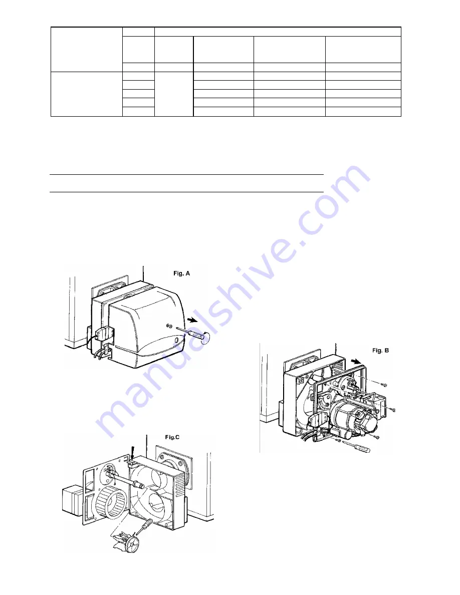
Most components can be inspected by removing the hood. To inspect the head you must disassemble the component-carrying
plate which can be hung on hung on the burner body in two different positions to make work as practical as possible. The
motor, transformer and solenoid valve are connected via a connector while the photo-resistor is push-locked into place.
MAINTENANCE
2) Undo the 4 screws of the plate, as indicated,
in order to access nozzle, electrodes and pre-
heater (if fitted).
1) Undo the lid screw to gain access to the
interior of the burner.
3) The plate must be hung up as illustrated in
fig. C.
- 12 -


