29
GB
L1 L2 L3
N
Sensor
Limiter
S1
Saunasteuergerät
control unit
U V W WB WM N
400 V AC 3N
N U V W
max. 9 kW
Sensor
Connection example of a sauna system with the Filius sauna heater
Caution! Always connect
the neutral wire N
Power
acc. DIN
Electr.
connection
Fuse
protection
in A
for cabin
volumes
Minimum
dimension
for ventilation
and bleeding
Connection
mains -
control unit
Connection
control unit -
heater
Power
switchgear
required
to be used with the control units
4.5 kW
3N AC
50 Hz
400 V
3 x 16
4 - 6 m³
35 x 5 cm
5 x 2.5²
5 x 1.5²
No
ECON D1
ECON D2
ECON H1
ECON H2
EMOTEC DC9000
EMOTEC DC9000 DB/DL/DLF
EMOTEC HCS9003
EMOTEC HCS9003 DB/DL/DLF
EmoTouch II PB/AF/GF
6.0 kW
6 - 8 m³
7.5 kW
7 - 10 m³
All information on cable cross-sections are minimum cross-sections in mm² copper line.
2000 W
2000 W
2000 W
3x G-Ltg
6,0 kW
U
V
W
N
PE
N
N
X
Y
Z
2500 W
2500 W
2500 W
3x G-Ltg
7,5 kW
U
V
W
N
PE
N
N
X
Y
Z
1500 W
1500 W
1500 W
3x G-Ltg
4,5 kW
U
V W
N
PE
N
N
X
Y
Z
Summary of Contents for Bi-O Filius
Page 2: ...2 Deutsch 3 English 20 o 37...
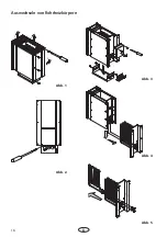
Page 16: ...16 D Auswechseln von Rohrheizk rpern 1 3 2 Abb 1 Abb 2 Abb 3 Abb 4 Abb 5...
Page 37: ...37 D Replacment of heating elements 1 3 2 Fig 1 Fig 2 Fig 3 Fig 4 Fig 5...
Page 45: ...34 RU DIN EN ISO 9001 2000 110 C 30 40 C 110 C 20 25 85 C 80 90 C...
Page 46: ...35 RU 8 VDE 0100 49 DA 6 VDE 0100 703 2006 2 5 10...
Page 47: ...36 RU DIN EN VDE 0100 T 703 40 170 C...
Page 48: ...37 RU S Guard...
Page 52: ...52 RU 4 3 4 4 2 5 2 2 3 3 3 3a 6 2 5 6 5 6 A Ansicht A 4 2 x 9 5 8 7 3 4 2 9 5...
Page 53: ...53 RU 5 7 5 cm 7...
Page 55: ...55 RU 4 3 4 4 2 5 5 2 2 3 3 3 3a 5...
Page 56: ...56 RU A Ansicht A 5 6 5 cm 8 6 7 4 2 x 9 5 9 8 3 4 2 9 5 6 7 2 6 7...
Page 57: ...57 RU 1 3 2 1 2 3 4 5...
Page 58: ...58 RU 2 1 3 4 5 6 180 1 2 3 4 5 7 8 9 10 3 mm 2 1 6 28 3 mm 6 7...
Page 59: ...54 RU 4 5 5 1 0 8 4 II Ill 10...
Page 60: ...44 RU 100 10...
Page 62: ...46 RU RMA RMA RMA 3 1 2 2 RMA...


