background image

17

EN

Important notice

• 

This device can be used by children aged 
8 upwards and by persons with physical, 
sensory, or mental disabilities, or who 
have inadequate experience and knowl-
edge if they are supervised or if they have 
received adequate instruction in how to 
use the device safely and understand the 
associated risks. 

• 

Children must be supervised to ensure 
they do not play with the unit. 

• 

Children and persons who have not re-
ceived proper instruction must not clean 
or service the system.

• 

Installation and connection to the infrared 
control unit must be carried out in accord-
ance with the connection diagram.

• 

Before the infrared radiator is operated via 
the controller, check that all connections 
or terminals are firmly connected with no 
risk of coming loose.

• 

The EU 60335-2-53 (VDE 0700 Part 53) 
regulations are to be observed for infrared 
cabins.

• 

Only the number of infrared radiators 
specified for the size of the cabin should 
be mounted in the infrared cabin. Please 
ask your cabin manufacturer or dealer.

• 

Use only a suitable control unit to control 
the infrared radiator. The control unit must 
be mounted in accordance with the instal-
lation instructions.

• 

 Attention: Covering the infrared radi-

ator causes a fire risk!

• 

The installation of the infrared radiator 
in the cabin must be carried out in such a 
way to assure even all-round heat for the 
user.

• 

The infrared radiator is not suitable to in-
stallation on the cabin ceiling and may not 
be mounted there.

• 

If the infrared radiator is installed in the 
back zone, then appropriate protective 
measures must be taken to ensure that the 
flocked protection grille cannot be pressed 
in unintentionally (e.g. a wooden grille 
mounted in front).

• 

Bear in mind that the main energy dis-
charge occurs through the infrared radia-
tion.

• 

Additionally, however, a thermal heat 
discharge arises at the vertically installed 
housing. This heat can overheat the sur-
rounding wood! Caution: fire risk!

• 

Ensure that this hot convection air can es-
cape by rising freely (ventilation).

• 

If necessary, appropriate steps should be 
taken (e.g. thermal protection slabs) to 
ensure that the wood is not exposed to 
inadmissible temperatures.

• 

The infrared radiator is equipped with a 
silicon connection cable. It should be con-
nected to the control unit as per connec-

Summary of Contents for IRS 40 RHK

Page 1: ...IRS 40 RHK Druck Nr print no 2934 2354 14 22 Technische nderungen vorbehalten Technical changes reserved D Montage und Gebrauchsanweisung Assembly and operating instruction EN RU Infrarotw rmestrahle...

Page 2: ...2 Deutsch 3 English 15 27...

Page 3: ...echnische Daten 7 Zubeh r optional 7 Interne Verdrahtung 7 Anschlussplan mit Steuerger t InfraTec Basic 8 Hinweis zum Elektroanschluss 9 Montage 10 12 Mindestabst nde 10 Einbaubeispiele 11 Recycling 1...

Page 4: ...unktion beeintr chtigen und ist nicht zul ssig Jegliche nicht autorisierte technische Ver nderung f hrt zum Verlust der Gew hr leistung Sehr geehrte Kundin sehr geehrter Kunde Sie haben ein hochwertig...

Page 5: ...angegeben Bitte fragen Sie Ihren Kabinenhersteller oder H ndler Allgemeine Sicherheitsbestimmungen F r die Regelung bzw Steuerung der Inf rarotstrahler ist ein geeignetes Steuerge r tzuverwenden Diese...

Page 6: ...e dass der Emitter im Infra rot W rmestrahler keinen mechanischen Belastungen St e Druck ausgesetzt wird Ist der Emitter einmal gebrochen was aber beim bestimmungsgem en Ge brauch unwahrscheinlich ist...

Page 7: ...1 5 m 94 7811 IR Steckmodul mit Adapterkabel PVC 25 cm 94 7812 IR Verbindungsleitung SIHF 3 m 94 7813 Technische Daten Elektrischer Anschluss 230V N 50 Hz Leistung 400W Gewicht ohneVerpackung ca 2 0 k...

Page 8: ...itter Verteilerblock Connection box max 3500 W total 230V Sensor bauseitige Lasterweiterung power rating extension by customer Hinweis Bei Anschluss die maximal zul ssige Belastung der Ausg nge im Ste...

Page 9: ...llten die Anschlussleitun gen durch Leerrohre gef hrt werden oder durch sonstige geeignete Ma nahmen gegen Besch digung gesch tzt werden Bei dem Anschluss von mehreren Strahlern an eine gemeinsame Lei...

Page 10: ...nmechanischenBelas tungen St e Druck aussetzen Bruchgefahr Achtung Achten Sie darauf den IR Strahler so zu installieren dass der Kabelanschluss nach unten ausgerichtet wird Mindestabst nde Der Mindest...

Page 11: ...ben 560 165 550 185 65 530 5 5 4 0 10 165 Abb 5 ACHTUNG Nicht f r den Einbau in die Kabinendecke geeignet Brandgefahr durch Hitzestau Ma e in mm Frontansicht Wandausschnitt mit Hinterl ftung Montage a...

Page 12: ...kleidet werden Abb 4 Die hei e aufsteigende Luft die durch die Erw r mung des Geh uses entsteht muss frei austreten k nnen Brandgefahr Inspizieren Sie die Kabine vor jeder Inbetriebnahme AchtenSieinsb...

Page 13: ...ycling Bitte diese Adresse zusammen mit der Montageanwei sung gut aufbewahren Damit wir Ihre Fragen schnell und kompetent beantwor ten k nnen geben Sie uns immer die auf dem Typen schild vermerkten Da...

Page 14: ...kte sind f r den St ckgut versand Palette konzipiert Wir weisen an dieser Stelle ausdr cklich darauf hin dass unsereVerpackungen nicht f r den Einzelversand per Paketdienst geeignet sind F r Sch den d...

Page 15: ...ries optional 19 Inner wiring scheme 19 Wiring diagram with control unit InfraTec Premium 20 Advice to electrical connections 21 Installation 22 24 Planning advice 22 Minimum distances Safety gaps 22...

Page 16: ...claims immediately with the delivering transport company or please consult the supplier who provided the equipment to you Caution Risk of fire by incorrect installation Make sure to read the installat...

Page 17: ...itable control unit to control theinfraredradiator Thecontrolunitmust bemountedinaccordancewiththeinstal lation instructions Attention Coveringtheinfraredradi ator causes a fire risk The installation...

Page 18: ...hanical stresses knocks pressure Risk of break age Although breakage is unlikely if it is used properly if the emitter should break re place it with a new one Caution fire risk in the case of a broken...

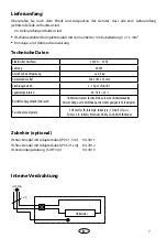
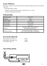
Page 19: ...daptor with cable 1 5 m 94 7811 IR plug adaptor with cable 25 cm 94 7812 IR connection cable 3 m 94 7813 Technical data Voltage power supply 230V N 50 Hz Nominal power 400W Weight excl packaging ca 2...

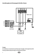
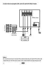
Page 20: ...ntrol unit outputs Observe the instructions in the control unit installation and operating manual Infratec Classic N N N N L L L L PE PE PE Licht LSG IR Strahler Netz IR Emitter IR Emitter IR Emitter...

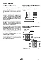
Page 21: ...corresponding ca ble with plug connect the IR radiator using this plug Otherwise you can alternatively use the special connection cable item 94 7813 for connection to the control unit Draw the connec...

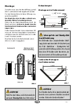
Page 22: ...nstallation and 9 cm for hori zontal installation See fig 4 The horizontal minimum distance between the emitter and all combustible parts must be 4 cm Fig 6 Make sure to provide sufficient ventilation...

Page 23: ...view Wall cut out with rear ventilation ATTENTION Not suitable for installation in the cabin ceiling Risk of fire due to heat congestion Fig 6 Fig 7 Flush mounted installation Vertical installation i...

Page 24: ...e connection must face up or as per cabin manufacturer s specifications the area above the radiator inside the wall mustbehollow Therisinghotairfromthe working radiator must be able to escape freely R...

Page 25: ...your questions quickly and compe tently please provide the information printed on the type shield including the model item no and serial no in all inquiries Equipment commissioning date ______________...

Page 26: ...roducts is designed for the ship ping of individually packed goods pallet We expressly point out that our packaging is not suitable for individual shipments via parcel post The manufacturer shall acce...

Page 27: ...27 RU 28 30 31 31 31 31 32 33 34 35 34 34 35 36 37 ASB 38...

Page 28: ...28 RU...

Page 29: ...29 RU 8 EU60335 2 53 VDE0700 53...

Page 30: ...30 RU...

Page 31: ...5 N L IR Emitter 3 3 x 1 5 1 5 94 7811 25 94 7812 3 94 7813 230 50 400 2 5 560 x 185 x 65 2 10 IR B IR C 20 C 50 C EOS EmoTec IR InfaStyle InfraStyle i InfraTec Classic EOS Econ I1 InfraTec Premium SB...

Page 32: ...N N N L L L L PE PE PE Licht LSG IR Strahler Netz IR Emitter IR Emitter IR Emitter IR Emitter IR Emitter Verteilerblock Connection box max 3500 W total 230V Sensor bauseitige Lasterweiterung power rat...

Page 33: ...33 RU 1 3 5 2 4 7 9 6 8 94 7812 2 2b 3 5 9 3 5 2b 3500 2 2b 94 7813 94 7811 94 7812 3500 5 9...

Page 34: ...34 RU 4 7 4 9 4 4 6 3 3 min 7 cm min 9 cm min 4 cm min 7 cm min 4 cm min 4 cm Kabelanschluss muss unten sein 4 0 10 4 0 10 30 50 10 20...

Page 35: ...35 RU 5 6 7 4 5 6 7 5 7 171 mm 15 mm 90 mm 6 160 mm 171 mm 15 mm 50 mm 40 mm 560 165 550 185 65 530 5 5 4 0 10 165...

Page 36: ...36 RU 4 5...

Page 37: ...37 RU EOS Saunatechnik GmbH Schneiderstriesch 1 35759 Driedorf Germany EOC 108811 928 7 495 66 55 192 8 800 1000 539 info eos sauna ru www eos sauna ru...

Page 38: ...38 RU ASB I II III IV V VI 24 www eos sauna com agb 08 2018...

Reviews: