9
EN
Abb. 7
Sicherungsschraube
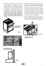
2. Open the terminal box at the rear side
of the heater and connect the power
supply cable in accordance with the
connection diagram (see chaper Electrical
Connection) as per power supply type.
The default connection diagram is also
attached inside terminal box of the heater.
ATTENTION: In the case of connection to
a 230V 1N AC power supply disregard the
default connection diagram and refer to
the special separately available connection
scheme.
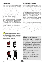
Terminal box cover
with spacer
Illust. 4
Terminal block
Lock nut
Cable gland
Illust. 5
3. Close the terminal box with cover using 2
fixation screws. Observe that the integrated
spacer faces outwards. See Illust. 4 for details.
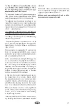
4. Hook the sauna heater into the wall moun-
ting using the mounting slots on the rear
wall. Make sure that the heater securely
hangs on the mounting bracket and the
spacer at the terminal box has a full contact
to the sauna wall. See Illust. 6. Observe that
the 18 cm floor gap is maintained.
5. Fasten the sauna heater to the wall mounting
through the hole located on the rear edge of
the oven using self-tapping screw (Illust. 7).
Illust. 6
Illust. 7
Securing screw
18 cm
wall-mounting bracket


