background image

User manual for

 XMR401HD

8

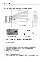
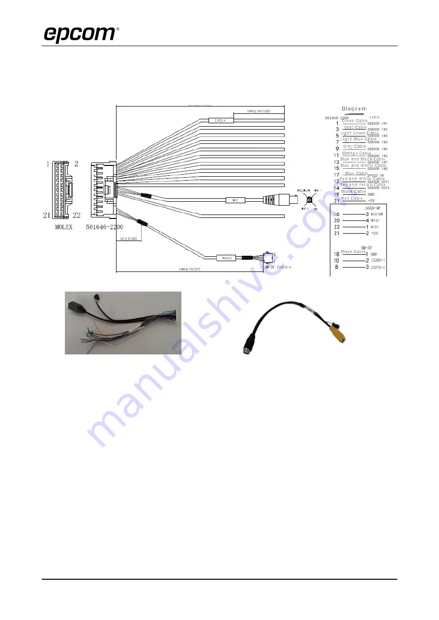
1.5. DEFINITION AND PICTURES OF EXTERNAL CABLES

ALARM CABLE DEFINITION

Alarm and Serial Cables

A/V OUT Cable

2. FREQUENTLY ASKED QUESTIONS

1)

The system can’t start?

Usually this problem results from the incorrect power connection. Please follow below steps to

check the power connection:
1.

Check the input power, whether the power wire is connected correctly, whether the ground wire is
connected back to the battery, and whether the fuse on the power wire is in good condition.

2.

Check whether the ACC signal wire input to the power is with voltage higher than 7 V.

3.

Check whether the device key is closed.

2)

The MDVR restarts uninterruptedly?

Please follow below steps to check it:

1.

Check whether the voltage of MDVR is insufficient. If the voltage is less than the start-up voltage of
the device, the device would always restart.

2.

The problem in hard disk/SD card may cause the failure to start. Take off the storage part and check

Summary of Contents for XMR401HD

Page 1: ...User manual for XMR401HD 1 User Manual For 05 Mobile Digital Video Recorder...

Page 2: ...to kindly aid the user for the operation for our MDVR The user should have a basic understanding of computer operation and basic knowledge of how to connect peripherals and make some settings Copyrigh...

Page 3: ...work of checking and maintenance should be done by qualified technicians and engineers We do not undertake any responsibility caused by unauthorized modifications 5 Requirements on Environment The equ...

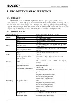
Page 4: ...de Easy Check CP4 mouse Video Input 4 channels WD1 1 channel 720P Output 1 channel Total Resource 4x25 FPS WD1 PAL 4x30 FPS WD1 NTSC 30FPS 720P Video Signal Standard Electrical level 1Vpp Impedance 75...

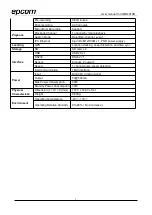
Page 5: ...on tracking speed detection and time sync Storage SD SD card x 2 Interface USB USB2 0 x 1 RS232 RS232 1 Sensor 8 inputs 2 outputs Speed 1 channel pulse speed detection Intercommunication I MIC interfa...

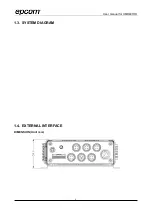
Page 6: ...User manual for XMR401HD 6 1 3 SYSTEM DIAGRAM 1 4 EXTERNAL INTERFACE DIMENSION Unit mm...

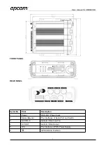
Page 7: ...NEL Serial No Print Description 1 Power DC 8 36 V Power Input 2 Sensor Serial The Interfaces of Serial Port and Switch 3 A V IN1 4 Audio Video Input 1 4 4 A V OUT Audio Video Output 5 IPC The Interfac...

Page 8: ...ectly whether the ground wire is connected back to the battery and whether the fuse on the power wire is in good condition 2 Check whether the ACC signal wire input to the power is with voltage higher...

Page 9: ...is set on 3 There must be video input into the channel for recording and it must record normally 5 The GPS works abnormally Please follow below steps to check it 1 Check whether the GPS antenna is in...

Reviews: