=== PROGRAM-MODE ===
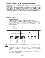
18 DISCONNECT TIME:
[ 40 ] sec.
( 1 sec. ... 130min.)
The time between disconnecting the capacitors to reduce the momentary
network capacitance.
Selection via
é
/
ê
. Save / continue with ENTER
19 DISCHARGE TIME:
[ 60 ] sec.
( 1 sec. ... 130min.)
This is the time for which an individual output is blocked between disconnecting
and connecting. It depends on the discharge device of the capacitor. The
discharge time of a conventional system without fast discharge resistors or
reactors should not be adjusted to less than the data sheet value of the used
capacitor.
Selection with buttons
é
/
ê
. Save /Continue with ENTER
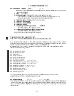
20 ALARM TEMPERATURE [ 55 ] °C
( 20...80 )°C
The alarm temperature programmed here is the temperature at which a
stepwise disconnection of the capacitors is performed. After 10 min. the
standard alarm relay of the controller (K21) will respond. At the same time,
the display shows the cause of the alarm (over temperature).
When the temperature drops again, the required branches are automatically re-
connected in steps.
Selection with
é
/
ê
. Save / Continue with ENTER
21 FAN TEMPERATURE
[ 30 ] °C
( 15...70 )°C
Threshold for the fan relay (K23) for control of a cabinet fan.
22 MESSAGE RELAY
[OFF ]
( 1...9 )
The message relay (K22) can be programmed for one of the following options
as required:
1 - OFF
2 - Supply: Message when active power is supplied.
3- Under current:
Message when the measuring current is not met.
Signal is generated when the current value
drops below the response sensitivity of the controller.
4 - Harmonics:
Message when the limiting value of the total harmonic
distortion factor (THD-V) is exceeded. This value can
be parameterized under ”38 Harmonics” (in %).
5 - ERROR - System current measuring
6 - ERROR - Com1 (interface error)
7 - ERROR - Com2 (interface error)
8 - ERROR - Com1/2 (interface error)
9 - C-DEFECT
- 16 -
S
U
H
E
E
Display:
Display:
Display:
Display:
Display:

