background image

24

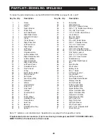
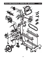
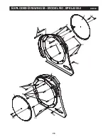
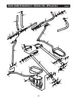
To locate the parts listed below, see the EXPLODED DRAWING on pages 25, 26, and 27.

P

ART

L

IST—

M

ODEL

N

O. EPEL4255.0

R0705A

1

1

Frame

2

1

Upright

3

2

Track

4

12

Nylon Washer

5

2

Pedal Disk

6

1

Left Side Shield

7

1

Right Side Shield

8

1

Generator Bracket

9

1

Crank

10

1

Crank Spacer

11

1

Right Pedal Arm

12

1

Left Pedal Arm

13

1

Right Pedal

14

1

Left Pedal

15

1

Drive Belt

16

1

Handlebar Axle

17

1

Left Handlebar Arm

18

1

Right Handlebar Arm

19

1

Left Handlebar

20

1

Right Handlebar

21

1

Right Pedal Cover

22

1

Left Pedal Cover

23

2

Handlebar Foam

24

10

Plastic Insert

25

1

Pulley

26

1

Water Bottle Holder

27

2

Wheel Spacer

28

2

Set Screw

29

4

Small Snap Ring

30

1

Generator

31

2

Wheel

32

1

Control Board

33

2

Pulse Grip

34

4

Grip Insert

35

4

Contact

36

4

Levelling Foot

37

1

Foot

38

2

Pedal Wheel

39

2

Handlebar Cap

40

4

Ramp Screw

41

4

Axle Cap

42

14

Bearing

43

8

Handlebar Bushing

44

2

Spacer

45

4

Snap Ring

46

4

Wheel Bearing

47

8

#10 x 3/4” Console Screw

48

4

3/8” x 1 1/4” Button Head Screw

49

4

1/4 x 3/8” Cap Screw

50

2

1/2” x 2” Button Head Screw

51

4

Crank Screw

52

4

#8 x 3/4” Screw

53

4

Wave Washer

54

14

#10 x 3/8” Pedal Screw

55

2

3/8” x 1” Shoulder Screw

56

4

1/4” x 3/4” Axle Screw

57

2

Bottle Holder Screw

58

4

3/8” x 5/8” Shoulder Screw

59

28

1/4” x 3/4” Button Head Screw

60

2

5/16” Nylon Locknut

61

2

5/16” x 3 1/2” Cap Screw

62

4

3/8” x 3/4” Cover Screw

63

4

Pedal Bushing

64

2

Long Side Shield Spacer

65

2

Key

66

4

Axle Washer

67

14

#10 Washer

68

1

Battery Pack

69

4

#6 x 1” Screw

70

2

1/2” Nylon Locknut

71

1

Tension Bolt

72

4

3/8” Nylon Locknut

73

1

Short Side Shield Spacer

74

1

Display Console

75

1

Control Console

76

1

Pulse Jumper Wire

77

1

Lower Battery Wire

78

1

Upper Battery Wire

79

1

Upper Controller Wire

80

1

Lower Controller Wire

81

1

Generator Coil Wire

82

1

Electromagnet Wire

83

1

Left Crank Arm

84

1

Right Crank Arm

85

4

3/8” Split Washer

86

4

#10 Star Washer

87

2

3/8” x 2 3/4” Shoulder Bolt

#

1

User’s Manual

Key No. Qty.

Description

Key No. Qty.

Description

Note: “#” indicates a non-illustrated part. Specifications are subject to change without notice. 

If replacement parts are needed, or if parts are missing or damaged, see HOW TO ORDER REPLACE-

MENT PARTS on the back cover of this manual. 

Summary of Contents for 1000 Ex Elliptical

Page 1: ...ial number in the space above for future reference QUESTIONS As a manufacturer we are com mitted to providing complete customer satisfaction If you have questions or if parts are damaged or missing PL...

Page 2: ...liptical Exerciser 5 How to Move the Elliptical Exerciser 6 How to Use the Console 8 Maintenance and Troubleshooting 20 Exercise Guidelines 22 Part List 24 Exploded Drawing 25 How to Order Replacement...

Page 3: ...ellip tical exerciser do not arch your back 11 If you feel pain or dizziness while exercising stop immediately and begin cooling down 12 Wear appropriate exercise clothes when using the elliptical exe...

Page 4: ...l the toll free telephone number on the front cover of this manual To help us assist you please note the product model number and serial number before calling The model number is EPEL4255 0 The serial...

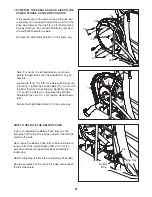
Page 5: ...he position shown Attach the Left Handlebar Arm to the Left Handlebar 19 with two 3 8 x 5 8 Shoulder Screws 58 Attach the Right Handlebar Arm not shown to the Right Handlebar 20 in the same way 2 Have...

Page 6: ...o the desired location and then lower the elliptical exerciser CAUTION To decrease the risk of injury bend your legs and keep your back straight Make sure to use your legs rather than your back to lif...

Page 7: ...7 NOTES...

Page 8: ...nce of the pedals as it guides you through an ef fective workout The console also offers two PULSE programs that automatically adjust the resistance of the pedals to keep your heart rate near a target...

Page 9: ...e CLEAR button This button is used to reset the console When this button is pressed the main display will be reset and the words PLEASE SELECT A PRO GRAM TO BEGIN will scroll across the main display N...

Page 10: ...e The display will change from one number to the other every few seconds Speed RPM The right end of the main display will show your pedaling speed in miles per hour or kilometers per hour and your ped...

Page 11: ...lms must be resting on the upper contacts and your fingers must be touching the lower contacts Avoid moving your hands When your pulse is detected the HEART RATE indicator above the main display will...

Page 12: ...e If you select a resis tance setting higher than 8 the indicators in all columns will shift downward until you select a lower resistance setting After every 30 seconds that you exercise a tone will s...

Page 13: ...he left column of the ma trix will flash During the last four seconds of the first segment the column to the right will also flash When the first segment ends a tone will sound and the column to the r...

Page 14: ...ix will flash During the last four seconds of the first segment the column to the right will also flash If the resistance of the ped als is about to change a series of tones will sound and the resista...

Page 15: ...main display then press the ENTER button Enter your age See step 3 on page 13 Enter your weight See step 4 on page 13 Enter a maximum heart rate setting Next the words PCT MAX RATE and the maxi mum he...

Page 16: ...may automatically de crease If this occurs see THE PULSE SENSOR on page 11 Follow your progress with the main display See THE MAIN DISPLAY on page 10 When you are finished using the elliptical ex erci...

Page 17: ...nsole See HOW TO ACTIVATE THE CONSOLE on page 9 Select the PLATEAU program To select the PLATEAU program press the PLATEAU button The indicator on the button will light and the word PLATEAU will appea...

Page 18: ...HOW TO ACTIVATE THE CONSOLE on page 9 Select the desired program Press the FOOTHILLS PEAKS or ALL TERRAIN button The indicator on the button will light and the word FOOTHILLS PEAKS or ALL TER RAIN wil...

Page 19: ...the total distance pedaled on the elliptical exerciser Press the ENTER button again and set a maximum program time for the programs The maximum program time for the programs can be from 10 minutes to...

Page 20: ...English system miles and pounds or the metric system kilometers and kilograms To change the system of measurement see step 7 on page 19 3 SYMPTOM THE PULSE SENSOR DOES NOT FUNCTION PROPERLY If the ha...

Page 21: ...the Tension Bolt 71 1 4 turn until the Drive Belt 15 stops slipping Retighten the four 1 4 x 3 8 Cap Screws and secure the Left Side Shield with the nine 1 4 x 3 4 Button Head Screws 59 Secure the Rig...

Page 22: ...sys tem your exercise must be aerobic Aerobic exercise is activity that requires large amounts of oxygen for prolonged periods of time This increases the demand on the heart to pump blood to the muscl...

Page 23: ...23 NOTES...

Page 24: ...4 1 4 x 3 8 Cap Screw 50 2 1 2 x 2 Button Head Screw 51 4 Crank Screw 52 4 8 x 3 4 Screw 53 4 Wave Washer 54 14 10 x 3 8 Pedal Screw 55 2 3 8 x 1 Shoulder Screw 56 4 1 4 x 3 4 Axle Screw 57 2 Bottle H...

Page 25: ...34 69 35 30 49 1 50 46 46 31 70 70 46 31 46 50 36 36 25 32 59 37 15 82 81 80 79 78 77 76 42 42 86 85 36 75 68 71 47 47 85 85 48 47 86 47 86 47 86 36 3 3 9 51 51 24 24 24 24 24 40 40 40 40 24 24 8 47 5...

Page 26: ...26 59 5 59 59 59 59 7 64 73 6 59 59 59 59 5 59 EXPLODED DRAWING B MODEL NO EPEL4255 0 R0705A...

Page 27: ...45 41 56 39 23 72 55 21 13 11 66 4 66 4 84 10 12 63 63 38 65 44 42 66 45 41 56 83 4 61 60 28 22 72 87 14 67 67 54 54 67 42 58 58 43 43 63 63 87 72 43 38 29 27 29 52 52 52 52 29 27 29 4 4 4 4 4 4 4 EX...

Page 28: ...to any product or damage to a product caused by or attributable to freight damage abuse misuse improper or abnormal usage or repairs not provided by an ICON authorized service center products used for...

Reviews: