background image

12

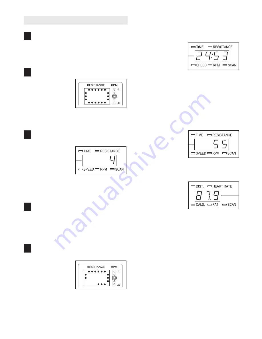
HOW TO USE THE MANUAL MODE

Begin pedaling to activate the console.

To activate the console, begin pedaling or push
any button on the console. After a few seconds,
the console displays will light. A tone will then
sound and the console will be ready for use.  

Select the manual mode.

When the power is
turned on, the
manual mode will
be selected. If you
have selected a
program, select
the manual mode
by pressing the Program Select button repeatedly
until a track appears in the matrix.

Begin pedaling and change the resistance of
the pedals as desired.

As you pedal,
change the resis-
tance of the ped-
als by pressing the
Resistance but-
tons. There are
ten resistance lev-
els. Note: After the buttons are pressed, it will
take a moment for the pedals to reach the select-
ed resistance level. 

Adjust the angle of the ramp as desired.

As you pedal, change the angle of the ramp by
pressing the Power Ramp buttons. Note: After
the Power Ramp buttons are pressed, it will take
a moment for the ramp to reach the selected
angle. 

Monitor your progress with the matrix and the
two displays.

The matrix
When the manual
mode is selected,
the matrix will
show a track rep-
resenting 1/4 mile.

As you exercise, the indicators around the track
will light in succession until the entire track is lit.
The track will then darken and the indicators will
again begin to light in succession.

The upper
display
—The
upper display will
show the elapsed
time, the resistance
level, your pedaling
speed, and your
pedaling pace, in revolutions per minute (RPM).
The display will change from one number to the
next every few seconds, as shown by the indica-
tors around the display. Note: When a program is
selected (except for heart rate program 1), the
display will show the time remaining in the pro-
gram instead of the elapsed time. Each time the
resistance of the pedals changes, the display will
show the resistance level.

If desired, you can
select a single
mode for continu-
ous display. Press
the left Mode button
repeatedly until the
desired mode indi-
cator is lit; make sure that the Scan indicator is
not lit.

The lower
display
—The lower
display will show
the distance you
have pedaled and
the approximate
numbers of 

calories

and 

fat calories you have burned (see FAT BURN-

ING on page 18). The display will change from
one number to the next every few seconds, as
shown by the indicators around the display. The
display will also show your heart rate when you
use the handgrip pulse sensor. 

If desired, you can select a single mode for con-
tinuous display. Press the right Mode button
repeatedly until the desired mode indicator is lit;
make sure that the Scan indicator is not lit.

5

4

3

2

1

Summary of Contents for E 760

Page 1: ...rial No _ Serial Number Decal beneath the frame QUESTIONS As a manufacturer we are com mitted to providing complete customer satisfaction If you have questions or if parts are damaged or missing PLEAS...

Page 2: ...N 4 ASSEMBLY 5 HOW TO OPERATE THE ELLIPTICAL EXERCISER 10 MAINTENANCE AND TROUBLESHOOTING 17 EXERCISE GUIDELINES 18 PART LIST 20 EXPLODED DRAWING 22 HOW TO ORDER REPLACEMENT PARTS Back Cover LIMITED W...

Page 3: ...the upper body arms when mounting dismounting or using the elliptical exerciser 11 If you feel pain or dizziness at any time while exercising stop immediately and cool down 12 The pulse sensor is not...

Page 4: ...parts that are labeled in the drawing below Handlebar Pulse Sensor Upper Body Arm BACK RIGHT SIDE Power Receptacle Wheel Pedal Fan Console Ramp Bookrack Upright Pedal Leg Leveling Foot LEFT SIDE Heal...

Page 5: ...ssembled If a part is not in the parts bag check to see if it has been preassembled M10 x 92mm Carriage Bolt 124 2 M6 Washer 102 2 M10 x 25mm Button Screw 123 3 M8 Washer 132 4 M8 x 35mm Button Bolt 1...

Page 6: ...t Slide the other Ramp Axle Cover 41 onto an M6 x 16mm Button Screw 103 and tighten the Button Screw into the open end of the Ramp Axle 39 Tubes 4 4 Slide an M6 Washer 102 onto an M6 x 16mm Button Scr...

Page 7: ...onto the short part of the Bolt Set 101 and tighten the short part of the Bolt Set into the long part Attach the other Chrome Tube not shown and the other Ramp Wheel not shown to the right side of th...

Page 8: ...9 10 15 15 16 2 9 Tab 116 8 15 7 11 17 12 117 91 16 91 2 9 Have another person hold the Left Handlebar 7 near the Upright 2 as shown Connect the left Pulse Sensor Wire 11 to the Pulse Extension Wire...

Page 9: ...lly insert all excess wiring down into the Upright 2 Attach the Console 3 to the Upright with four M4 x 16mm Screws 99 Be careful to avoid pinching the wires Do not pinch the wires during this step 3...

Page 10: ...e by a metal screw Some 2 pole receptacle out let box covers are not grounded Contact a quali fied electrician to determine if the outlet box cover is grounded before using an adapter EXERCISING ON TH...

Page 11: ...offers six preset programs Each pro gram automatically changes the resistance of the ped als and prompts you to increase or decrease your pace as it guides you through an effective workout In additio...

Page 12: ...light in succession until the entire track is lit The track will then darken and the indicators will again begin to light in succession The upper display The upper display will show the elapsed time t...

Page 13: ...r heart rate is not shown make sure that your hands are positioned as described Avoid moving your hands excessively or squeezing the metal contacts too tightly For optimal performance periodically cle...

Page 14: ...egment The program will continue until the resistance set ting for the last segment is shown in the Current Segment column of the matrix and no time remains in the program Note During the program you...

Page 15: ...s repeatedly to change the target heart rate if desired and then press the Enter Program Start button Note See EXERCISE INTENSITY on page 18 for heart rate guidelines If heart rate program 2 is select...

Page 16: ...i cator lights maintain your current pace Important The pace guide is intended only to provide a goal Make sure to pedal at a pace that is comfortable for you The program will continue in this way unt...

Page 17: ...erciser rocks slightly on your floor during use turn one or both of the leveling feet under the rear stabilizer until the rocking motion is elimi nated HOW TO MOVE THE ELLIPTICAL EXERCISER Stand in fr...

Page 18: ...ardiovascular sys tem your exercise must be aerobic Aerobic exer cise is activity that requires large amounts of oxygen for prolonged periods of time This increases the demand on the heart to pump blo...

Page 19: ...les Stretch With one leg in front of the other reach forward and place your hands against a wall Keep your back leg straight and your back foot flat on the floor Bend your front leg lean forward and m...

Page 20: ...dal Leg 48 1 Left Pedal 49 1 Right Pedal 50 2 Ramp Wheel 51 4 Wheel Cover 52 4 Pedal Leg Bearing 53 1 Lower Wire Harness 54 2 Foot 55 2 Rear Side Shield Bracket 56 2 Front Side Shield Bracket 57 1 Upp...

Page 21: ...crew 116 4 M8 x 42mm Button Bolt 117 2 M8 x 35mm Button Bolt 118 3 M10 Split Washer 119 2 M4 x 50mm Screw 120 1 M4 x 25mm Screw 121 10 M4 x 14mm Screw 122 4 M8 Split Washer 123 3 M10 x 25mm Button Scr...

Page 22: ...15 15 16 18 17 19 19 20 21 22 23 24 25 26 27 28 99 99 99 115 125 116 91 91 117 117 91 91 99 99 99 99 119 121 121 127 121 120 121 121 99 121 99 121 125 127 127 127 125 123 118 118 123 118 114 114 127...

Page 23: ...66 67 68 69 70 71 72 73 74 74 75 76 76 77 78 79 81 80 82 83 84 85 86 86 86 86 87 87 87 87 88 90 89 124 90 101 101 101 101 103 103 102 102 103 103 104 104 90 100 100 96 97 99 99 127 126 99 95 95 109 12...

Page 24: ...ty does not extend to any product or damage to a product caused by or attributable to freight damage abuse misuse improper or abnormal usage or repairs not provided by an ICON authorized service cente...

Reviews: