37
No obstante, las baterías se suelen suministrar con un
estado de carga superior al 80%.
3.
Desconectar la acometida de la instalación y asegurarse
que no hay tensión en los puntos a manipular.
4.
Siguiendo las indicaciones del manual del Variador de
Frecuencia, espere el tiempo prudencial requerido y
realice las operaciones pertinentes para poder acceder
a los conectores P (+) y N (-) del variador (bus de continua
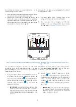
del variador de frecuencia). Ver Fig. 24
However, the batteries are usually supplied with a state of
charge upper than 80%.
3.
Disconnect electric mains, ensuring there is not
voltage left in the nodes about to be handled.
4.
Wait a reasonable time according to your VVVF drive
handbook. Get access to P (+) and N (-) drive terminals
(DC-link). See
Error! Reference source not found.
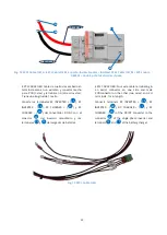
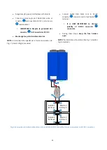
Fig. 27. Conexión al variador de velocidad con los terminales del CABLE OEG/ Frequency controller connection
trough CABLE OEG.
Con un polímetro verifique que la tensión residual en los
conectores P(+) y N(-) se encuentra en niveles seguros
(menor de 50V)
. Si la tensión es menor que 50 V continúe al
siguiente punto; sino, espere.
5.
En la parte inferior del Convertidor DC/DC se encuentra
el conector hembra para la conexión al variador de
frecuencia, “Inverter POWER”
. Con el CABLE OEG se
proporciona el conector macho. Asegúrese del correcto
cableado entre el conector
y el variador de
velocidad. Ver Fig. 24
i)
IMPORTANTE
: la alimentación del variador se va a
realizar, a partir de ahora, a través de esta conexión.
Asegúrese de que no existe ninguna conexión en la
entrada habitual de alimentación del variador, L
1
/R,
L
2
/S, L
3
/T.
Check that residual voltage between P(+) and N(-) is within
the safe level (
lower than 50V
) with the aid of a
multimeter. Continue it is safe. If not, wait.
5.
Connect “Inverter POWER” terminal at DC/DC
converter
to the VVVF drive through CABLE OEG.
The female connector is located on the underside of
DC/DC converter. CABLE OEG provides male
connector. Be sure that the connection is correct
between
connector and the frequency controller.
See
i)
IMPORTANT:
From now on, the VVVF is going to
be supplied through this connection. Make sure
there are no other connections at the usual VVVF
supply input, L
1
/R, L
2
/S, L
3
/T.
DC / AC
AC / DC
R
b
ra
ke
C
bus
L
1
/R
L
2
/S
L
3
/T
VVF
Variable Frequency Drive
DB
P1
P
(+
)
N
(-
)
U
V
W
5
9
5
9
5
9
5
Summary of Contents for P2S Series
Page 1: ...1 Manual de instalaci n Installation guide P2S Series plug single phase P2S powered by...
Page 2: ...2 Versi n 4 6 June 2018 Epic Power Converters S L...
Page 9: ...9 Fig 3 Convertidor DC DC 5k5 5k5 DC DC Converter 0 1 2 3 4 6 10 9 7 8 5...
Page 55: ...55 Dimensiones EPCL 5K5 EPCL 5k5 dimensions...
Page 56: ...56 6 6 Dimensiones del cargador de bater as 6 6 Battery charger dimensions...
Page 58: ...58 Inversor TS 700 TS 700 Inverter...
Page 59: ...59 6 8 Dimensiones del Controlador de carga solar 6 8 Solar charge controller dimensions...
Page 61: ...61 6 9 2 Bastidor bater as Small 4x1 6 9 2 Small batteries rack 4x1...
Page 62: ...62 6 9 3 Bastidor bater as Medium 6 9 3 Medium batteries rack...

