background image

Owner's Manual for EPILOG Legend Model 6000  


December, 2000

voltage for your building

. Do not proceed if the voltage is incorrect.  Call Epilog technical support at 

303-215-9171. 

2)


Locate the power cord in the accessory kit

.  The end with the recessed terminals connects to the 

Legend.  Locate the power entry receptacle next to the “Power” label on the left side of the machine.  

Insert the power cord firmly into the receptacle.  

3)


Plug the machine into your wall power outlet, and 

turn the machine on

.  The power switch is next to 

where the power cord connects to the Legend. The machine should beep and the carriage should 

move towards home position. 

CONFIGURING YOUR COMPUTER – PRINT DRIVER INSTALLATION 

Epilog provides two “printer drivers” for use with Windows based computers.  The first is the standard 

“Legend Engraver Driver”  and the second is the “Legend Stamp Driver”.  The drivers are included in the 

accessories kit on a 3.5-inch diskette labeled EPILOG.  With the computer turned on and Windows open, 

insert the diskette into your 3.5-inch disk drive to install the print drivers. 

Your computer must have 

Windows 95 or Windows 98 already installed. 

INSTALLING THE EPILOG LEGEND PRINT DRIVERS 

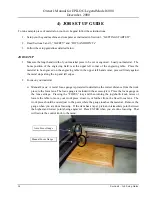
1)


Click on the “START” button at the bottom left of your screen. 

2)


Click on “SETTINGS”. 

3)


Click on “PRINTERS”. 

4)


Double Click on  “ADD PRINTER”. 

5)


In the ADD PRINTER WIZARD click on “Next”. 

6)


Normally you should select “Local Printer”, and then click “Next”.  

7)


Click on “Have Disk”. 

8)


In the “Install From Disk” window your 3.5” floppy drive should be pre-selected in the “Install From 

Manufacturer’s Disk” box.  If it is, click on OK.  If necessary, change the drive designation, and then 

click on “OK”. 

9)


Click on Legend under “Manufacturer’s”, then click on “Legend Engraver”, and then click on “Next”. 

10)


Under “Available Ports” highlight LPT1: Printer Port, then click on “Next”. 

11)


Click on “Yes” or “No” depending on whether you want this to be the default printer.  “Yes” is 

recommended.  Click on “Next”. 

12)


Click on “No” to printing a test page, then click on “Finish”.  Your “Legend Engraver” print driver is 

now installed. 

13)


Follow the above procedure again to install the “Legend Stamp” driver. 

14)


It is recommended that you turn your computer off and restart it after you have installed a new print 

driver. 


Section 1 – Getting Started 


Summary of Contents for Legend 6000

Page 1: ...Owner s Manual for EPILOG Legend Model 6000 Revision E December 2000 500 Corporate Circle Suite L Golden CO 80401 Phone 303 277 1188 Fax 303 277 9669 Technical Support 303 215 9171 ...

Page 2: ...E STAMP DRIVERS 17 USING THE LEGEND ENGRAVER PRINT DRIVER 17 USING THE EPILOG LEGEND RUBBER STAMP PRINT DRIVER 21 6 USING THE EPILOG LEGEND 25 KEYBOARD COMMANDS 25 LEGEND LCD MENU HEADINGS 28 LEGEND LIQUID CRYSTAL DISPLAY 29 OPTICS 34 LOADING YOUR WORK 35 OPERATION 35 7 ENGRAVING MACHINE MAINTENANCE 36 CLEANING IMPORTANT 36 LASER TUBE 38 8 SPEED AND POWER RECOMMENDATIONS 39 35 WATTS OR LESS 39 50 ...

Page 3: ...OBLEMS 69 15 SERVICING THE LEGEND 73 SERVICE MODULE LOCATION DIAGRAM 74 CONTROLLER 75 POWER SUPPLY 76 LASER MODULE 77 RF MODULE 78 KEYBOARD DISPLAY 80 X BEAM 80 16 UPGRADING THE OPERATIONAL FIRMWARE 82 INSTALLING FLASHMASTER ONTO YOUR COMPUTER 82 INSTALLING NEW LEGEND FIRMWARE ONTO YOUR COMPUTER 82 INSTALLING NEW FIRMWARE FROM YOUR COMPUTER TO YOUR LEGEND 83 17 SPECIFICATIONS 86 LEGEND 32 SPECIFIC...

Page 4: ...o use the Legend as soon as you read the first four sections Then you can refer to topics in the remaining chapters as you work STRUCTURE OF THE MANUAL SECTIONS 1 4 How to uncrate and set up your Legend important safety information you need to know before you use it the do s and don ts of operating the Legend and a brief user s guide to running your first job SECTIONS 5 7 Basic Legend operations a...

Page 5: ...en platform the machine is sitting on locate the edge that is secured with two screws Loosen and remove the screws and remove the wooden 2 x2 6 Under the machine all the way under locate the ramps They will be wrapped in plastic Remove them and place the metal hooks into the slots on the pallet These ramps will allow you to roll the machine off the pallet There is a left and a right ramp The raise...

Page 6: ...d through the ethernet port The network port allows for higher transfer rates as well as allowing for data to be transferred from any of several computers A network is also the best way to connect multiple Legends Serial Port Storage Slot Network Port Parallel Port The data port connections are on the right side of the machine towards the rear The previous drawing shows the location of all the por...

Page 7: ...ower should be mounted outside your building for noise considerations The blower should not be more than twenty feet from the Legend You should provide a rigid smooth duct from the blower to the vicinity of the Legend The Legend 32 requires 400 CFM at 6 of static pressure and the Legend 24 requires 400 CFM at 4 of static pressure Remember to put the blower switch in an obvious and accessible place...

Page 8: ...C single phase electrical outlet The electrical outlet should be fitted with a NEMA L6 15R receptacle HUBBEL 4560 or equivalent If not already available a licensed electrician prior to the arrival of the Epilog installation technician must perform the proper circuit wiring The location of the power cord receptacle of the Legend is shown in the drawing below and is located on the left side of the m...

Page 9: ...ch disk drive to install the print drivers Your computer must have Windows 95 or Windows 98 already installed INSTALLING THE EPILOG LEGEND PRINT DRIVERS 1 Click on the START button at the bottom left of your screen 2 Click on SETTINGS 3 Click on PRINTERS 4 Double Click on ADD PRINTER 5 In the ADD PRINTER WIZARD click on Next 6 Normally you should select Local Printer and then click Next 7 Click on...

Page 10: ... any of its protective covers while the unit is plugged in DO NOT attempt to defeat the door and window interlocks DO NOT look directly into the beam of the Laser Diode Pointer Red Dot Pointer DO NOT operate the Laser Diode Pointer Red Dot Pointer without the machine s focus lens in place If the unfocused beam strikes a reflective surface it could be directed out of the cabinet The standard refere...

Page 11: ...ngraving materials are inherently combustible and while the objective of most engraving and cutting operations is to vaporize material without burning it is easy to ignite a flame Usually this is a simple flare of burning gases issuing from the focused spot on the work piece which follows the moving spot and which extinguishes itself as soon as the laser beam is modulated off But should the work p...

Page 12: ...ngraving laser when either the cabinet door or window is opened A visible emission indication when the Laser Diode Pointer Red Dot Pointer is operating There is an LED indicator on the machine s front panel 21 CFR 1040 10 requires that certification identification and warning labels be placed on laser products Reproductions of labels on the Legend Model 6000 Laser System follow with their location...

Page 13: ...ctive Housing Safety Label This label is located on the right side of the machine s cabinet below the access door A special fixture is required to defeat the interlocks on the Model 6000 product 5 Aperture Safety Label This label is located inside the machine s cabinet at the right rear above the aperture through which the laser and Laser Diode Pointer Red Dot Pointer beams enter the cabinet 6 Ele...

Page 14: ...0 December 2000 10 Section 2 Safety HIGH VOLTAGEINSIDECABINET DISCONNECT POWER BEFORE OPENINGPANEL 7 Fire Safety Label This label is located on the top of the laser bay cover at the rear of the machine FIREHAZARD DONOT OPERATE MACHINEUNATTENDED ...

Page 15: ...l This label is located directly below the Warning label item 8 on the left side of the cabinet LASER RADIATION DO NOT STARE INTO BEAM OR VIEW DIRECTLY WITH OPTICAL INSTRUMENTS CLASS 3A LASER PRODUCT 4 mW CW MAXIMUM 630 680 nm 10 Non interlocked Protective Housing Safety Labels 2 These labels replace items 3 above One is located on the steering mirror cover inside the laser bay at the rear of the ...

Page 16: ...ty Label This label replaces item 4 above and is located on the right side of the machine s cabinet below the access door A special fixture is required to defeat the interlocks on the Model 6000 product CAUTION INVISIBLE LASER RADIATION WHEN OPEN AND INTERLOCK DEFEATED AVOID EYE OR SKIN EXPOSURE TO DIRECT OR SCATTERED RADIATION ...

Page 17: ...ing or cutting Vinyl NEVER operate your machine unattended There is a significant risk of fire if the machine is set improperly or if the machine should experience a mechanical or electrical failure while operating NEVER engrave or cut acrylic material unattended This is a popular material to laser however its fumes are extremely flammable and cause flare up in your machine Always watch carefully ...

Page 18: ...left hand corner pressed firmly against the metal stops along the top and left edges 2 Focus on your material Manual Focus A metal focus gauge is provided to determine the correct distance from the work piece to the focus lens The focus gauge is included in the accessory kit Place the focus gauge on the lens carriage Pressing the FOCUS key and then turning the jog shuttle knob raises or lowers the...

Page 19: ...G THE EPILOG LEGEND of this manual for step by step instructions 3 Turn on the exhaust fan 4 Close the door and press the GO key 5 Layout your Artwork in your drawing program ARTWORK LAYOUT Now go into your drawing program CorelDRAW etc and set the page size to the same dimensions of the material piece you have loaded Then create your design to be engraved or cut within the page outline You can en...

Page 20: ...practice at high speed and low power to mark only the tape 3 For more information on the print setup read Section 5 Using the Legend Print Driver of this manual Now press print and you are engraving and cutting REMEMBER THE STEPS 1 Turn on the power to the engraver and wait for a Beep to note the machine is ready 2 Insert the item to be engraved make sure table is low enough to accommodate piece 3...

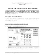
Page 21: ...s The Legend Stamp driver is used to engrave rubber stamp formats INSTALLING THE STAMP DRIVERS The installation of both of these drivers is detailed in Section 1 under subheading Configuring Your Computer Print Driver Installation of this manual The two drivers are explained in further detail regarding their properties in the following subsections USING THE LEGEND ENGRAVER PRINT DRIVER The Legend ...

Page 22: ... You can use vector mode to cut through acrylic or wood mat board plastic cork paper etc Only the Vector Speed and Vector Power bars will be enabled when you have selected Vector under Job Type Set the Speed and Power bars to the appropriate settings for the material that you are cutting When using vector mode it is necessary to design your job to give the intended result Objects and text should b...

Page 23: ...ay contact the carriage prior to reaching the correct focus point Longer focal length optics are available for doing deeper parts Contact your Epilog Representative for more information 6 COMPUTER CONTROLLED SPEED POWER When this box has an X in it the speed and power are controlled from the computer The Legend will disregard any attempt to alter speed or power from the control panel on the engrav...

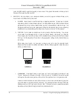
Page 24: ...nt to change the speed and power for a color that is already in the list just click on the entry you want to change Now move the speed and power controls to the new values and click on the MODIFY button If you have made a mistake click on the entry you want to remove and then click on the DELETE button c DITHER COLORS If you have an X in this box the colors will be given a texture If the box is em...

Page 25: ... FOR STAMPS 1 Set up your artwork in Corel so that your computer image looks like the image that you want to stamp Areas to be stamped should be black with the area to be removed white 2 If you want to have the laser cut the individual stamps out from the sheet place a 001 outline with no fill around each stamp You can use rectangles or you can use the pen tool to draw a tight outline that follows...

Page 26: ...asteful Design Fence Line 001 Laser Cut Line 001 Example 2 Example 1 Please remember the fence must have a 001 outline and must completely enclose your design You can cut out individual stamps by using a 001 outline within the fence Once your artwork is set up you need to specify how you want the machine to cut the stamp The Legend Stamp print driver setup window is shown below ...

Page 27: ...click the cursor in the Configurations box and type in a custom name of up to 18 characters long spaces are allowed When you click the SAVE button this custom setup will be saved When you are in the Legend Stamp s setup window you can click on the Configurations pull down menu to retrieve your different custom stamp job setups 4 RASTER Controls the laser speed and power for the engraving portion o...

Page 28: ...e 1 or 2 will produce a narrow character A high value 6 or 7 will produce wider or bolder character A value of 1 is recommended 8 RATE AUTOMATIC RATE varies the laser cutting frequency for the vector portion of the job Generally on rubber sheets put an X in the rate automatic box 9 AUTOFOCUS Putting an X in the auto focus box enables the auto focus feature of the Legend if you have the auto focus ...

Page 29: ...JOG SHUTTLE ROUND KNOB The Jog Shuttle is used to raise and lower the table as well as to change settings like speed and power The keys and menus are used to specify what the Jog Shuttle will do These functions are described in detail later in this Section The rate of change caused by the inner ring depends on how fast you spin it The direction depends on whether you spin it clockwise or countercl...

Page 30: ... to determine the correct distance from the work piece to the focus lens The focus gauge is included in the accessory kit The work piece should be raised just to the point where the gauge touches your work piece Remove the gauge when you are done focusing Press ENTER when you are done focusing That will restore the control knob to the menu ENTER AND ESCAPE MENU CONTROLS The Legend has direct keys ...

Page 31: ...sted lighter or darker Insert a small flat blade screwdriver into the slot just below the surface of the keyboard and rotate the adjuster to get the best display contrast for your work environment POINTER This is simply a visible reminder that the Laser Diode Pointer Red Dot Pointer is turned on This Laser Diode Pointer Red Dot Pointer is much like the hand held laser pointers and has a bright red...

Page 32: ...bers Press Arrow Keys to Move Through Fields Subnet Mask Turn Knob to Select Numbers Press Arrow Keys to Move Through Fields Gateway Networking Save Settings Highlight and Press Enter Options Not Enabled Reserved for Future Use Dwell mSec Not Enabled Reserved for Future Use Frequency kHz Not Enabled Reserved for Future Use Offset Not Enabled Reserved for Future Use Assist Gas Cutting Turn Knob to ...

Page 33: ...o the desired numeric value The choices range from 1 0 to 100 A lower number reduces the depth of cut A higher number increases depth of cut 3 Diode Pointer The DIODE POINTER setting allows for manually turning ON or OFF the Laser Diode Pointer Red Dot Pointer This visible output beam is much like the hand held laser pointers and has a bright red beam This beam allows the operator to visually note...

Page 34: ...o Focus to work when the Auto Focus command is selected in the print driver If Auto Focus is not selected in the print driver the Auto Focus feature will not be enabled Do not enable the Auto Focus option unless your machine is actually equipped with the auto focus sensor Erratic operation will result 2 Air Assist Use the down arrow key to highlight AIR ASSIST and press ENTER This option enables t...

Page 35: ...iginal default position upon power down CUTTING Currently only the frequency and smoothing commands are operational The others are not enabled and are reserved for future use 1 Frequency This control allows direct setting of the pulsing of the laser in vector mode The control allows setting from ten hertz to five thousand hertz The lower frequencies are normally used for perforating an edge when y...

Page 36: ...S will result in the laser returning to the default settings the next time that you power down the Legend b Y Home This function calibrates the home position of the machine relative to the top table guide Refer to the X Home procedure above to set the Y Home position i Incrementing the Y Home counter will shift the position of the engraved box up towards the table guide by 001 inch ii Decrementing...

Page 37: ... to complete a job Depending on the type of image that you are producing the RAMP COMPENSATION can be adjusted to provide the best combination of quality and speed Fine details or demanding graphics should be run using the factory settings Large block lettering or less demanding images can be run at values of 1 or 2 to increase production speeds i This parameter is set at the factory at a setting ...

Page 38: ... enabled Reserved for future use OPTICS The Legend is equipped with a two inch focal length lens as standard equipment The lens assembly is removed by loosening the captive screw in the center of the optics plate Other lenses are available as options for special situations A one and a half inch lens is available for fine detail work and a two and a half inch lens is available for cutting thick mat...

Page 39: ...aust fan Now go into your drawing program CorelDRAW etc and set the page size to the dimensions of the practice piece you have loaded Then enter your name in half inch text anywhere on the page Once you have the image ready to engrave print to the machine through the Legend print driver using the standard print command Your drawing program should give you the opportunity to do a print setup where ...

Page 40: ... the next page clean each of the bearing tracks shown A cotton swab is perfect for cleaning out the inside of the grooved tracks About once every three months you should lubricate the bearings Using the lubricant Syringe from your accessory kit apply a thin bead of grease on the bearings shown in the diagram on the next page Each bearing has two grease points The grease should go down inside the s...

Page 41: ...fully Rubbing alcohol should be used only to remove fingerprints If you run out of the cleaner supplied by Epilog acetone can be used as a temporary measure but should not be used for regular cleaning as it contains impurities which can contaminate the optics If you run out of solvent pure ethyl grain alcohol such Golden Grain and Everclear are highly recommended because of their pure nature and b...

Page 42: ...lar motions When you are done be careful to remove any cotton threads that may have snagged on the mountings and allow the optics to dry before you operate your engraver LASER TUBE The laser tube used in the Legend does have a maximum service life The amount of engraving time that you get from a tube will depend to a large extent on how much material you remove from your plaques Typical operating ...

Page 43: ...Table one provides starting points for 35 watt lasers or less Table 2 provides starting points for 50 watts or greater 35 WATTS OR LESS 300 DPI ENGRAVING SPEED POWER 600 DPI ENGRAVING SPEED POWER CUTTING SPEED POWER 1 4 Wood 20 100 30 100 10 100 1 4 Acrylic 90 100 90 60 10 100 Anodized Aluminum 90 80 90 55 N A Brass Painted 90 60 90 55 N A Corian Or Avonite 10 100 20 100 N A 1 8 Delrin 20 100 30 1...

Page 44: ...3 8 Wood 60 100 70 100 20 100 3 8 Acrylic 100 30 100 25 15 100 Anodized Aluminum 100 50 100 40 N A Brass Painted 100 35 100 30 N A Corian Or Avonite 40 100 50 100 N A Delrin Seals 50 100 60 100 50 100 Glass 70 100 75 100 N A Laserable Plastic 100 40 100 35 75 30 Leather 100 45 100 40 N A Marble 50 100 60 100 N A Matboard 100 45 100 40 75 40 Melamine 70 100 80 100 N A Rubber Stamps 40 100 50 100 50...

Page 45: ...G WITHOUT A HUB This method involves direct printing from your computer s network card to the Legend This method is similar to printing through the parallel port with the distinct advantage that it allows you to use a much longer cable up to 328 feet than a standard parallel printing cable allows REQUIREMENTS 1 A 10Base T Ethernet network card installed in your Windows 95 98 computer 2 A crossover...

Page 46: ...n current connections to your local area network or other devices that you may already have This method has the advantage of isolating your Legend engraver from the network if you wish but does not isolate your computer from your network This is a simplified printing solution that does not affect your server REQUIREMENTS 1 A 10Base T Ethernet network card installed in your Windows 95 98 computer 2...

Page 47: ...ter Ask your network administrator to configure your server to work with any number of computers and or as many Legend engravers as you wish Your network administrator will need to provide the appropriate configurations for the IP Address Subnet Mask and Gateway Address on the Legend engraver INSTALLING INTELLISCRIBE Server less printing is accomplished by installing third party software INTELLIsc...

Page 48: ...o restart your computer 5 Restart your computer 6 Click on the Windows Start button 7 Select Programs INTELLIscribe to start the INTELLIscribe program A series of dialog windows will appear to set up your Legend The following window will appear 8 From the Menu bar select Printers then select Add or Update Virtual Printer Port The following window will appear 9 Type the word Legend in the Name box ...

Page 49: ...caused from the number in the Address box being different from the number in the IP Address box in your Legend laser They must match exactly 11 Select the Protocol down arrow and select LPR LPD The Port setting will automatically be properly set to 515 12 Click on the Add Destination button The address that you typed in above window will be displayed in the Destination s box 13 Single click on the...

Page 50: ...0 46 Section 9 Network Printing This window will now appear as follows 14 Click Next The following window appears 15 Single click to highlight 192 168 98 1 LPR LPD 515 in the address box 16 Click on LPD Queue Name 17 Type the word Legend into the empty field ...

Page 51: ...f your LPT1 port 20 Click on the Windows Start button 21 Select Settings and Printers 22 Double click on the Legend print driver icon 23 In the Legend Engraver window click on Printer and then click on Properties 24 In the Legend Engraver Properties window click on the Details tab The following window appears 1 Make sure INTELLIscribe INTELLIscribe Virtual Port appears in the Print to the followin...

Page 52: ... using the following driver box 4 Click on Okay Click on the down arrow to select the Legend Engraver if it does not already appear 5 Close the Legend Engraver window and you are ready to print over the network INTELLIscribe Software Contact Information Brooks Internet Software 1 800 523 9175 email sales brooksnet com www brooksnet com ...

Page 53: ...going to vector cut Extruded is less expensive than cast and also has a lower melting point that produces an almost flame finished edge when cut with the Legend ACRYLIC ENGRAVING TECHNIQUES Most acrylic is engraved on the backside to produce a look through effect from the front surface Remove the back protective cover layer before engraving Leave the top protective cover layer on so that it remain...

Page 54: ...ety of colors and can usually be easily engraved with a CO2 laser Black anodized aluminum is great to work with because it turns white when lasered Black anodize provides the best contrast of all of the colors of anodized aluminum Some colors of anodize red for instance will not turn completely white when laser engraved Red anodize will produce a light pink color Performing a second pass can see s...

Page 55: ...at appears to be fat or has a balloon appearance to it you are probably using too much power Reducing the power will bring back the nice sharp images that are normally produced with painted brass It is possible to laser bare un coated brass and apply an oxidizing agent to the engraved area to produce a black image This process is the same as the process used when rotary engraving brass and using a...

Page 56: ...t build up easily and it should not prevent you from engraving onto full bottles of vine champagne or other filled glass bottles Laser engraving filled bottles is a very popular method of creating custom presentations for special occasions The laser will not damage the liquid inside the bottle and as long as you are not completely engraving away a large section of bottle you have very little chanc...

Page 57: ...l of laser engraving NOTARY SEALS DELRIN ENGRAVING Notary seals can be easily manufactured using 1 16 inch thick delrin plastic A seal consists of two pieces a male die and a female die both shown below The male die consists of white lettering on a black background and the female die is an inverted and mirrored image of the male Inverting and mirroring are easily accomplished in most graphics soft...

Page 58: ...peed and power settings Use the guidelines in this manual as a starting point when determining the correct speed and power settings If you do not get acceptable initial results with the recommended speed and power settings start experimenting by first changing only the power setting If adjusting the power setting does not work start over and adjust only the speed setting Once you have acceptable r...

Page 59: ...r engraving PVC will void your warranty WOOD Solid Wood Manufactured Wood Products Engraving Vector Cutting Cleaning Color Filling SOLID WOOD Wood is by far the most laser friendly material available It can be engraved or cut very easily When engraved lighter colored woods like cherry or maple produce very nice contrast where the laser burns away the wood This high visual contrast is what makes li...

Page 60: ...r of these two woods is a light red We recommend stains that are clear allowing the natural color to show through Alder isn t quite as expensive as Cherry and it is a little more readily available Walnut is a dark brown in color and has a greater density than either Cherry or Alder Maple is light blonde in color and has a density that is even greater than Walnut It is important to mention the dens...

Page 61: ...om a dark color like red to a light color like yellow then engrave it This will create a shading effect that is almost 3 D in its appearance WOOD VECTOR CUTTING TECHNIQUES Legends are ideal for cutting through solid wood material The thickness of the wood that you can cut varies with the wattage of the laser and the hardness of the wood but in general you can cut approximately inch wood with a 25 ...

Page 62: ...FILLING TECHNIQUES Color filling engraved areas of wood adds either greater contrast or a splash of color to your wood presentation Normally color filling is not required for lighter colored wood materials such as maple or cherry but walnut can often benefit from adding a black color fill to provide more contrast You will need to take some precautions when color filling wood because if you are not...

Page 63: ...nd then run it The name of the job will show up at the bottom of the status bar MULTIPLE JOB MODE If there are jobs in memory select the JOBS menu heading and press the ENTER key The list of valid jobs in memory will drop down Select the one you want and press ENTER This will give you the options of Run View or Delete Select the one you want and press ENTER If you select Run the machine will begin...

Page 64: ... it is a comfortable reach 2 Put the optical plate up against the second bearing block and tighten the holding screw 3 Space the primary and secondary heads about 16 inches apart and place the connecting strut in between the heads Align the holes in the end of the strut with the holes on the carriages and insert and tighten the thumbscrews Please see the drawing on the next page ARTWORK LAYOUT Lay...

Page 65: ...Owner s Manual for EPILOG Legend Model 6000 December 2000 Section 12 Optional Equipment 61 Connecting Strut Correctly Assembled Double Head Double Head Installation Optical Plate ...

Page 66: ...hment is flush to the engraving table at all three pin positions 4 There is a motor on the rotary attachment with a plug on the end Plug the rotary into the mating connector located at the inside front left hand corner of the engraver This connector is oriented so that you cannot install it backwards unless you push really hard 5 The rotary attachment is now installed Turn the power on 6 The engra...

Page 67: ...eft side of the attachment 5 If you are engraving a mug with a handle the two drive wheels can be reduced in width by removing the two thumbscrews on the inside of each wheel ARTWORK LAYOUT 1 2 3 4 1 There are no special requirements for laying out jobs for the rotary The left margin of your job layout corresponds with the left edge of the fixture If you place your work at the top edge of the job ...

Page 68: ...onnect it The connection point to the Legend from the compressor is on the back panel The Legend uses a rigid plastic quick release connector Simply push in the supply hose from the compressor and it is attached You will need to plug the compressor into a wall plug for power Please verify the voltage listed on the compressor matches your building power In the upper right corner of the engraving ca...

Page 69: ...menu is at the top center of the display when you turn your machine on Do not enable the auto focus option unless your machine is actually equipped with the auto focus sensor Erratic operation will result Once you have enabled the option in the Legend you can use the auto focus by clicking on the auto focus box in the print driver when you are ready to send the Legend a job The auto focus can be t...

Page 70: ...ODUCTS WEBSITE Laserbits com ACRYLIC Acrylic Idea Factory 6669 C Peachtree Industrial Blvd Norcross GA 30092 Phone 800 543 9253 Fax 770 447 1113 LASER ENGRAVABLE COATED METALS Identification Plates Inc 1555 High Point Drive Mesquite TX 75149 9009 Phone 800 395 2570 Fax 972 216 1555 Victory 1820 N Major Avenue Chicago IL 60639 Phone 800 327 5578 Fax 773 637 7799 R S Owens Co 5535 North Lynch Avenue...

Page 71: ... Heirloom 333 E 4th Street Loveland CO 80537 Phone 970 667 4222 Fax 970 667 8880 Kentucky Woodcrafts Co P O Box 220 McKee Industrial Park McKee KY 40447 Phone 800 354 0196 Fax 606 287 8047 Lee s Wood Products 31 Smithers Street P O Box 159 Rocky Mount VA 24151 Phone 800 552 5337 Fax 540 483 4645 Stanton Manufacturing Lake Road 54 15 Lake Ozark MO 65049 573 365 2441 MIRRORED ACRYLIC Alenite Dodge 5...

Page 72: ...x 7065 Alogonquin IL 60102 Phone 815 477 0778 Fax 815 477 1210 Johnson Plastics 9240 Grand Avenue South Minneapolis MN 55420 3604 Phone 800 869 7800 Customer Service Fax 612 888 4997 FLAT GLASS Gold Coast Graphics 15841 Graham Street Huntington Beach CA 92649 888 733 0061 PEN PENCIL SETS IMARK Pen Co 3008 Pleasant Valley Lane Arlington TX 76015 Phone 817 465 6681 Fax 817 465 7411 RUBBER STAMP MATE...

Page 73: ...ed images will not vector Filled or solid images will not vector outlines only If you are using Corel 3 0 or Corel 5 0 verify that line width is 007 or less If you are using Corel 6 0 or Corel 7 0 the line width is DPI dependent If you are vectoring at 600 DPI then your line width must be 001 If you are vectoring at 300 DPI then your line width must be 003 Problem Engraver beeps and displays IDLE ...

Page 74: ... it is not revision G1 then contact Corel for the free upgrade Be prepared to supply Corel with your software serial number If you are using Corel 6 0 or 7 0 there are three settings in Corel that require the proper setting Put some type of design on your screen a basic square will do Then follow the instructions below Click on File Print Options Then Options page Then under Special Settings you w...

Page 75: ... other pertinent information Problem Image at the wrong location on the work piece Solution 1 Verify that the page size in Corel does not exceed the maximum engravable area of the machine 2 Verify that the page size in Corel matches the piece size in Print Setup If you have a page size of 2 X3 and a piece size in Print Setup of 24 X 18 then it will place the 2 X 3 in the center of the 24 X 18 area...

Page 76: ...of this problem is that the depth of engraving starts out uniform and correct but then varies either on the right side or at the bottom Solution At the home position put on your focus gauge and manually raise the table Focus key and rotate knob clockwise to where it just touches the gauge Shut off the machine and with your hand move the carriage to each of the other three corners of the table The ...

Page 77: ...ents are modular and can be replaced with a phillips head screwdriver or allen wrench WARNING Any servicing of the equipment should be done with the power cord disconnected from the machine Injury or death may occur if you attempt to service the machine with power connected The machine must be unplugged from the wall socket providing electrical power See the Diagram on the next page for the locati...

Page 78: ... Model 6000 December 2000 74 Section 15 Servicing the Legend SERVICE MODULE LOCATION DIAGRAM Cont r ol l er Cover Cont r ol l er Bay Laser Cover Laser Bay Power Suppl y Bay Power Suppl y Cover 100 W at t RF Cover 100 W at t RF Dr iver ...

Page 79: ...nplug the power cord from the machine or from the wall Demate the four connectors shown in the diagram below Then remove the screws shown in the diagram The captive screws are inside the machine and the four Phillips screws are on the outside The assembly can now be lifted up and out of the machine Then install the replacement Please be careful to make sure all the connectors are fully seated Plea...

Page 80: ...ver across the top of the cabinet see diagram on page 58 The laser cover has a connector that must be demated Press on the tab to release it To remove the power module loosen and remove the four phillips head screws on the outside of the machine shown in the drawing below Demate the two connectors shown in the drawing Then loosen the two captive screws across the top of the module Remove one final...

Page 81: ...will need to disconnect before you can set the cover aside The laser on your machine will resemble one of the two shown in the drawing below There are differences in appearance that do not effect servicing First remove the electrical connectors then the three allen head screws shown in the drawings The RF connection on the 50 100 watt lasers can only be removed once the laser is lifted out of the ...

Page 82: ...self 50 W at t air cool ed conf igur at ion The RF driver for the 50 watt is located to the right of the laser under the laser cover To service the RF remove the laser cover The cover is held in place with four or five phillips head screws The RF is held in place by three or four Allen head screws on the top and three or four hex nuts on the bottom as shown in the following diagram You will also n...

Page 83: ...ated on the bottom of the machine in the base pedestal To service the RF first remove the cover The cover is held in place with phillips head screws The RF is held in place by four large phillips head screws They are located two per side just inside the handles shown in the drawing The unit is can now be pulled partially out of the machine so the electrical connections can be demated There are thr...

Page 84: ... inside the Legend cabinet To remove service this module first if you have not already done so turn the machine off and unplug the power cord from the machine or from the wall Open the large door and gently pull the beam forward until it is a comfortable reach Loosen the phillips head screw on the left of the beam and the two captive screws on the right of the beam shown in the drawing on the next...

Page 85: ...EPILOG Legend Model 6000 December 2000 Section 15 Servicing The Legend 81 Disconnect cable Remove Clamp Remove the cable track Air Assist Only Captive screws two places Phillips Screw one place REPLACING THE BEAM ASSEMBLY ...

Page 86: ...om your computer to your Legend 2 Install new Legend firmware onto your computer The new Legend firmware is sent to you as a compressed file that needs to be extracted decompressed onto your hard drive before you can download it to your Legend 3 Install the new firmware from your computer to your Legend You will use FlashMaster to download the new firmware to your Legend NOTE If you already have F...

Page 87: ... exe file before trying to upgrade The Unzip process will convert the Legendxxx exe file into a file with a hex extension Use only the file with the hex extension to upgrade your Legend INSTALLING NEW FIRMWARE FROM YOUR COMPUTER TO YOUR LEGEND Prior to starting FlashMaster the user should ensure that the Legend is turned on and that it is connected to the computer by either the parallel port or ne...

Page 88: ... name is required If the user wishes to program the Legend over the network the TCP IP address of the Legend in the Target field Once the target is set the Go button can be pressed Sending the update to the Legend over the parallel port takes about 4 5 minutes The computer and the Legend should not be disturbed during this time On a Windows 95 98 computer the Progress field will properly indicated...

Page 89: ...act of re programming itself with the upgrade version of its firmware The front panel will say Programming Machine DO NOT DISTURB DO NOT POWER DOWN THE LEGEND DURING THIS TIME If you lose power or purposefully power down the Legend during this time your controller board in the Legend will be ruined and will have to be replaced This operation will take about 90 seconds After programming is complete...

Page 90: ...bient temperature is 85 F 27 C COMPATIBILITY The Epilog Legend has been designed as an open architecture product The Legend will work with many popular graphics engineering and specialty software products To benefit from all the functionality that was built into the Legend a Windows based PC is recommended The print driver that is shipped with the Legend offers a host of unique features and only w...

Page 91: ...end uses the latest technology providing a powerful tool that is simple to setup and operate The Legend can mark engrave and cut a variety of non metallic materials The laser beam itself is invisible The beam is about half the diameter of a 2 pencil Unfocused it will just make an ugly burn leaving lots of charred material behind The focus lens gives the beam an hourglass shape At the center point ...

Page 92: ...sion FCC Notice NOTE This equipment has been tested and found to comply with the limits for a Class A digital device pursuant to Part 15 of the FCC rules These limits are designed to provide reasonable protection against harmful interference when the equipment is operated in a commercial environment This equipment generates uses and can radiate radio frequency energy and if not installed and used ...

Reviews: