Pg. 9
©2014 Episode™
Pg. 8
©2014 Episode™
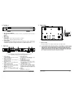
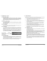
Episode amplifiers are designed to help deliver a great audio experience that makes your music come alive for
years to come. However, where you place the amplifier can have a large effect on the performance that you
receive and the life of the unit.
•
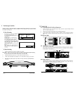
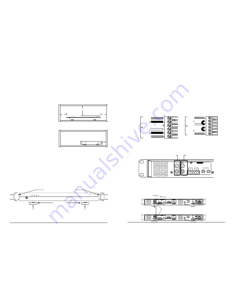
Be sure that the unit is in a well-ventilated area
that provides adequate cooling.
•
Do not block the cooling vents located on both
sides of the unit.
•
Do not place the unit on carpeting or any
similar material.
•
Do not install the unit near a source of heat, or
in an extremely humid or wet location.
•
If your installation lacks good air flow (such as
solid cabinet doors or wall-mounted racks), it
may be necessary to create ventilation to allow
outside air into the space.
•
Allow a minimum of 5” of free air space above
the unit.
•
Allow a minimum of 3” of free air space on
either side of the unit. (Does not apply to rack
mounting)
9. Positioning the Amplifier
P
OW
ER
2
1
PR
O
T
-
20
-
10
C
L
I
P
-
30
E
C
A
-7
0A
M
P
-
2D
-
300A
3i
n
.
3i
n
.
5i
n
.
M
i
n
i
m
u
m
of 3"
free
a
ir s
pa
ce o
n
e
a
ch side.
M
i
n
i
m
u
m
of 5"
free
a
ir s
pa
ce
ab
o
v
e.
9.1. Shelf Mounting
9.2. Rack Mounting
1.
Remove the amplifier’s four feet from the bottom of the chassis.
Note: DO NOT place the screws back into the chassis. Without the feet, the length of the screw may
touch internal components and affect the performance of the amplifier.
2.
Attach the included rack-mount ears to the front sides of the amplifier chassis.
3.
Securely mount the amplifier into an equipment rack. The amplifier will occupy 1U of rack space.
4.
Even though the amplifier produces very little heat, it is always wise to leave ventilation between
components.
P
OW
ER
2
1
PR
O
T
-
20
-
10
C
L
I
P
-
30
E
C
A
-7
0A
M
P
-
2D
-
300A
Re
m
o
v
e Feet
Att
a
ch E
a
rs usi
n
g Su
ppl
ied Scre
w
s
(
4 o
n
E
a
ch
)
2i
n
.
10. Connections
10.1. Terminating Wire in Set-Screw Connectors
1.
Strip the outer jacket of the cable (if applicable) back about 2”, and then strip the insulation of each wire
back ¼“ to expose the bare copper.
2.
Loosen the set screws on the connector using a 1/8” flat blade screwdriver.
3.
Twist the copper strands in conductor each clockwise, insert them into the correct holes, and tighten
the screws. Do not allow any strands of copper to touch and cause short circuits between the termi-
nals.
10.2. Balanced Input
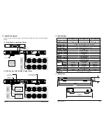
Use the balanced input to connect balanced or unbalanced cables to the amplifier.
Positi
v
e
(
+
)
N
eg
a
ti
v
e
(-)
Shie
l
d
CH
1
CH
2
Shie
l
d
Positi
v
e
(
+
)
N
eg
a
ti
v
e
(-)
Positi
v
e
(
+
)
N
eg
a
ti
v
e
(-)
CH
1
CH
2
Positi
v
e
(
+
)
N
eg
a
ti
v
e
(-)
Shie
l
d
Shie
l
d
Note Jumper between Shield and Negative (-)
10.3. Unbalanced Connections
The unbalanced Line IN input utilizes standard RCA cables for connection of sources. Connect a
source to each channel through its respective mono input. Use the Loop Out ports to connect to
more amplifiers or other equipment.
L
OO
P
OU
T
OUTPUTS
CAUTION:
INPUTS
ON
115
/
230V
OU
T
IN
A
U
T
O
ON
P
OW
ER
MO
DE
ANSI/UL STD.60065
Intertek
WARNING:
AVIS:
LEVEL
0V 0V
7
0V
7
0V
O
F
ON
LY
TYPE.
ATTENTION:
CH
1
CH
2
CH
2
CH
2
CH
1
CH
1
CH
2
CH
1
OFF
MASTER
POWER
F
U
SE TYPE:
T4AL 250V
T8AL 250V
VOLTAGE
SWITCH
E330247
Unbalanced
Loop Out 1 & 2
Unbalanced
Line IN 1 & 2
10.4 Using Loop Out
The Loop Out connections on the ECA-70AMP-2D amplifier may be used to send audio signal to
other equipment, or to the other channel of the amplifier. The Loop Out will carry audio signal out
from the unbalanced input OR the balanced input of the channel.
LOOP OUT
OUTPUTS
CAUTION:
INPUTS
ON
115/230V
OUT
IN
AUTO
ON
POWER
MODE
LEVEL
0V 0V
70V
70V
OF
ONLY
TYPE.
ATTENTION:
CH1
CH2
CH2
CH2
CH1
CH1
CH2
CH1
OFF
MASTER
POWER
FUSE TYPE:
T4AL 250V
T8AL 250V
VOLTAGE
SWITCH
E330247
From Source
Balanced or unbalanced input can be looped out
LOOP OUT
OUTPUTS
CAUTION:
INPUTS
ON
115/230V
OUT
IN
AUTO
ON
POWER
MODE
LEVEL
0V 0V
70V
70V
OF
ONLY
TYPE.
ATTENTION:
CH1
CH2
CH2
CH2
CH1
CH1
CH2
CH1
OFF
MASTER
POWER
FUSE TYPE:
T4AL 250V
T8AL 250V
VOLTAGE
SWITCH
E330247
Connect Channel 1 Loop Out to Channel 2 Loop In
for two channels with one source, or to other equipment

