Contacts us : email :
sales@epochloadcell.com
, Ph: 080-23481364
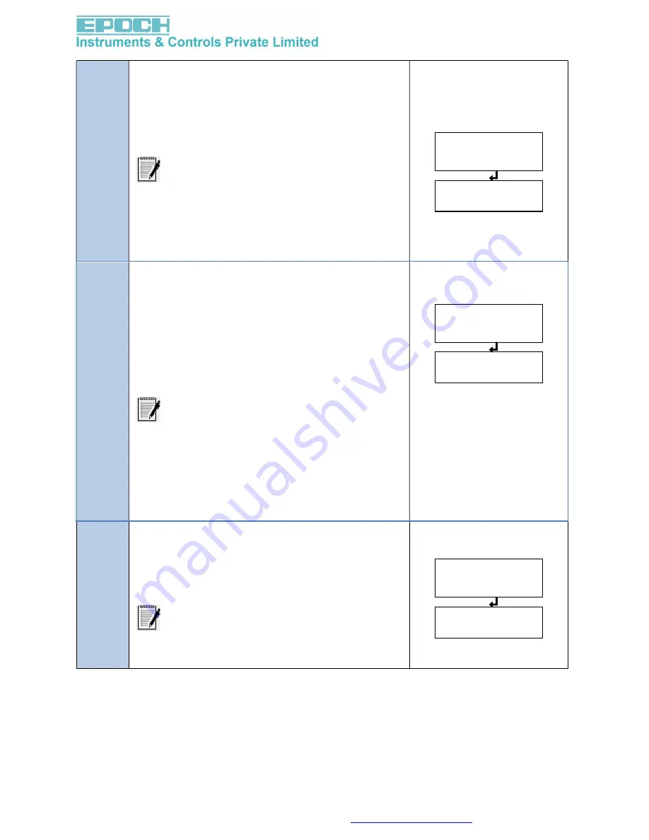
A-dEF
Lo
A-oFF
001.00
A-SPn
010.00
4.
Navigate to
Analog Default Value (A-dEF)
and
press
ENTER/TARE
.
This provides safety to Analog Output during
error conditions. The user can select what
value of Analog Output should be during error
conditions.
The available modes are,
Low Value (4 mA / 0 mA) -> ‘Lo’.
High Value (above 20 mA i.e.,22.05 mA)
-> ‘HI9H’.
Value at Previous stage -> ‘LASt’.
5.
Navigate to
Analog Offset (A-oFF)
and press
ENTER/TARE
.
This provides the Analog Output starts range.
Here, user can set the positive or negative
offset.
Before entering into “
A-oFF”
press left key to
Select positive (“pos”) or negative (“nEg”)
analog offset. “nEg”means –ve LED will be On.
The available modes are,
If the offset is “pos” means then analog
output range starts from positive 001.00
kg to analog span value.
If the offset is “nEg” means then analog
output range starts from negative 001.00
kg to analog span value.
6.
Navigate to
Analog Span (A-Spn)
and press
ENTER/TARE
.
This provides the Analog Output end range.
Here, user can set the weight at which can get
the max analog output.
This menu is restricted to the max
capacity value under calibration.


