Installation
EP-3S1A
Page 3-9
MODEM_IN
: Telephony Connector
Pin1(Audio_in), Pin2/Pin3(GND), Pin4(Mic-out to Modem)
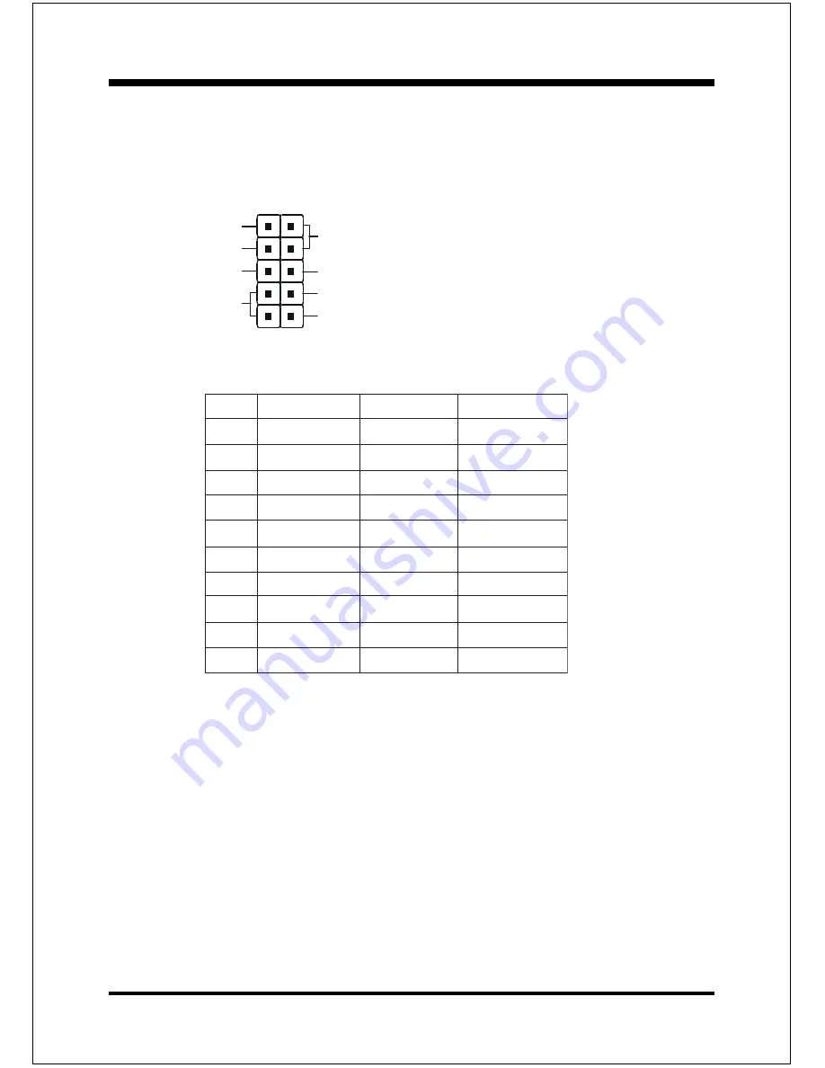
USB Conn.
: USB3 and USB4 Connector for optional cable.
#
N
I
P
r
o
l
o
c
e
ri
W
e
m
a
N
l
a
n
g
i
S
t
n
e
m
m
o
C
1
d
e
R
c
c
V
r
e
w
o
P
e
l
b
a
C
2
e
ti
h
W
a
t
a
D
-
a
t
a
D
3
n
e
e
r
G
a
t
a
D
+
a
t
a
D
4
k
c
a
l
B
d
n
u
o
r
G
d
n
u
o
r
G
e
l
b
a
C
5
k
c
a
l
B
d
n
u
o
r
G
d
n
u
o
r
G
e
s
a
C
6
k
c
a
l
B
d
n
u
o
r
G
d
n
u
o
r
G
e
s
a
C
7
k
c
a
l
B
d
n
u
o
r
G
d
n
u
o
r
G
e
l
b
a
C
8
n
e
e
r
G
a
t
a
D
+
a
t
a
D
9
e
ti
h
W
a
t
a
D
-
a
t
a
D
0
1
d
e
R
c
c
V
r
e
w
o
P
e
l
b
a
C
USB port header pin descriptions.
1
VCC
VCC
GND
GND
-Data
-Data
+Data
+Data
5
6
10
Summary of Contents for EP-3S1A
Page 6: ...EP 3S1A Page Left Blank ...
Page 14: ...Introduction EP 3S1A Page 1 8 Figure 5 System Block Diagram System Block Diagram ...
Page 17: ...Installation EP 3S1A Page 3 1 Section 3 INSTALLATION ...
Page 18: ...Installation EP 3S1A Page 3 2 Figure 1 EP 3S1A Detailed Layout ...
Page 32: ...Installation EP 3S1A Page 3 16 Page Left Blank ...
Page 61: ...Drivers Installation EP 3S1A Page 5 2 Page Left Blank ...
Page 73: ...Appendix EP 3S1A A 12 Page Left Blank ...


