Installation
EP-3WXA/4/4Y
Page 3-4
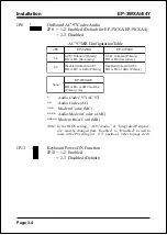
JP8
On Board AC’97 Codec Audio
JP8 = 1-2 Enabled (Default for EP-3WXA/EP-3WXA4)
= 2-3 Disabled
1
JP13
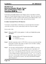
Keyboard Power-ON Function
JP13 = 1-2 Enabled
= 2-3 Disabled (Default)
1
AC’97/MR Configuration Table
8
P
J
A
X
W
3
-
P
E
4
A
X
W
3
-
P
E
2
-
1
)
y
r
a
m
i
r
P
(
d
r
a
o
b
n
O
7
9
'
C
A
)
y
r
a
d
n
o
c
e
S
(
C
M
r
o
R
M
)
y
r
a
m
i
r
P
(
d
r
a
o
b
n
O
7
9
'
C
A
)
y
r
a
d
n
o
c
e
S
(
C
M
r
o
R
M
3
-
2
7
9
'
C
A
d
r
a
o
b
n
O
d
e
l
b
a
s
i
D
)
y
r
a
m
i
r
P
(
C
M
A
r
o
C
M
r
o
R
M
7
9
'
C
A
d
r
a
o
b
n
O
d
e
l
b
a
s
i
D
)
y
r
a
m
i
r
P
(
C
M
A
r
o
C
M
r
o
R
M
e
n
o
N
Y
4
A
X
W
3
-
P
E
e
b
t
s
u
m
C
M
A
r
o
C
M
r
o
R
M
y
l
n
o
)
y
r
a
m
i
r
P
(
*
Audio Codec’97 (AC’97)
**
Audio Codec (AC)
***
Modem Codec (MC)
**** Audio/Modem Codec (AMC)
***** Modem Riser Card (MR)
Note:
In the BIOS setting, “AC97 Audio” of “Integrated Peripher-
als” must be changed from “Enabled” to “Disabled” as well to
come with JP8 setting (at “2-3” position). (refer to page 4-14).
Summary of Contents for EP-3WXA
Page 6: ...EP 3WXA 4 4Y Page Left Blank ...
Page 14: ...Introduction EP 3WXA 4 4Y Page 1 8 Figure 5 System Block Diagram System Block Diagram ...
Page 17: ...Installation EP 3WXA 4 4Y Page 3 1 Section 3 INSTALLATION ...
Page 18: ...Installation EP 3WXA 4 4Y Page 3 2 Figure 1 EP 3WXA 4 4Y Detailed Layout ...
Page 28: ...Installation EP 3WXA 4 4Y Page 3 12 Page Left Blank ...
Page 54: ...BIOS EP 3WXA 4 4Y Page 4 26 Page Left Blank ...
Page 56: ...Drivers Installation EP 3WXA 4 4Y Page 5 2 Page Left Blank ...


