BIOS
EP-6WEA4/4I
Page 4-16
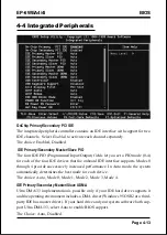
Onboard Parallel port
This field allows the user to configure the LPT port.
The default is 378H / IRQ7.
378H: Enable Onboard LPT port and address is 378H and IRQ7.
278H: Enable Onboard LPT port and address is 278H and IRQ5.
3BCH: Enable Onboard LPT port and address is 3BCH and IRQ7.
Disabled: Disable Onboard LPT port.
Parallel Port Mode
This field allows the user to select the parallel port mode.
The default is ECP+EPP.
Normal: Standard mode. IBM PC/AT Compatible bidirectional parallel port.
EPP: Enhanced Parallel Port mode.
ECP: Extended Capabilities Port mode.
EPP+ECP: ECP Mode & EPP Mode.
EPP Mode Select
This item allows you to determine the IR transfer mode of onboard I/O chip.
options: EPP1.9, EPP1.7.
ECP Mode USE DMA
This field allows the user to select DMA1 or DMA3 for the ECP mode.
The default is DMA3.
DMA1:
This field selects the routing of DMA1 for the ECP mode.
DMA3:
This field selects the routing of DMA3 for the ECP mode.
PWRON After PW-Fail
The system will stay of or power on after a power interrupte.
The default is Fomer-Status.
Fomer-Status: Stay off or power on depend on system safe shut-down or
power fail.
ON:
System always power on after a power interrupte.
OFF:
System always stay off after a power interrupte.
Game Port Address
Select an address for the Game port.
The choice: 201, 209, Disabled.
Summary of Contents for EP-6WEA4
Page 6: ...EP 6WEA4 4I Page Left Blank ...
Page 14: ...Introduction EP 6WEA4 4I Page 1 8 Figure 5 System Block Diagram System Block Diagram ...
Page 17: ...Installation EP 6WEA4 4I Page 3 1 Section 3 INSTALLATION ...
Page 18: ...Installation EP 6WEA4 4I Page 3 2 Figure 1 EP 6WEA4 4I Detailed Layout ...
Page 58: ...BIOS EP 6WEA4 4I Page 4 28 Page Left Blank ...
Page 60: ...Drivers Installation EP 6WEA4 4I Page 5 2 Page Left Blank ...
Page 72: ...Appendix EP 6WEA4 4I A 12 Page Left Blank ...

