Stand 26.11.08, SB 55 SV, Drills
Page 23 of 37
4
Handling
4.1 Safety
Only use the machine if the following conditions are achieved completely:
The machine is applied correctly
The machine is in a technical faultless condition
All safety devices are correct mounted and active
You have red, understood and observed the user manual
If failures during use encounter you, remove them immediately. Stop the machine
directly by a function failure and ensure them against undeliberate or
unwarranted resetting.
4.2 Control and indicator elements
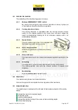
The control elements are located:
At control panel at the face side of the head
At table and column
4.2.1
Control elements electrical
The relevant control elements fort he machine operator are located at the drill
head. In the face side of the head are grouped:
EMERGENCY STOP control
Speed choice switch
Turning direction choice switch
Switch for machine light
Switch for coolant pump
4.2.2
Control elements mechanical
More control elements at the drill head are:
Feed lever three - armed
Depth Stop and display
Chip protection
Belt cover
Control elements of the table and column are the:
Table height adjustment
Table pivoting arrangement
Table tilting arrangement
Summary of Contents for SB 55 SV
Page 30: ...Stand 26 11 08 SB 55 SV Drills Page 30 of 37 7 Exploded drawing 7 1 Exploded drawing actuator ...
Page 32: ...Stand 26 11 08 SB 55 SV Drills Page 32 of 37 9 Exploded drawing 9 1 Exploded drawing stand ...
Page 34: ...Stand 26 11 08 SB 55 SV Drills Page 34 of 37 11 Circuit diagram 11 1 Circuit diagram SB 55 SV ...


