background image


26.01.07, SBS 32, Drills 


Page 23 from 33 


4.2 

Control and inidcator elements 

 
The control elements are located at: 
 

  At the control panel at the face side of the head 

  At table and column 


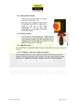
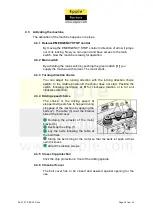
4.2.1  Control elements electrical 


The relevant control elements fort he machine operator are located at the drill 
head. In the face side of the head are grouped: 


  Main switch with emergency Stop function 

  Switch for machine light 


Additionally there is build in a turning direction choice switch at the left 
side of the drilling head. 


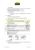
4.2.2  Control elements mechanical  


More control elements at the drilling head are:  


  Feed lever 3 - armed 

  Depth display and arrester 

  Chip protection 

  Belt protection cover 


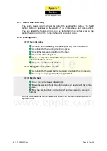
Control elements at the table and the column are: 


Table height adjustment


  Table swivel arrangement 

  Table tilt arangement 


Summary of Contents for SBS 32 400 V

Page 1: ...26 01 07 SBS 32 Drills Page 1 from 33 User manual Drill SBS 32 400 V Keep for future reference ...

Page 2: ...bition instruction and warning signs 12 1 7 Safety check at the machine 13 1 8 Personal protective equipment for special work 14 1 9 Safety during the use of the machine 15 1 10 Safety during general maintenance work 16 1 10 1 Breaking and assuring the machine 16 1 10 2 Use of hoisting devices for attendance work 16 1 10 3 Mechanic attendance work at the machine 17 1 11 Accident report 17 1 12 Ele...

Page 3: ...ch 24 4 3 3 Turning direction choice 24 4 3 4 Driving speed choice 24 4 3 5 Close chip protection 24 4 3 6 Close belt cover 24 4 3 7 Activating 25 4 3 8 Deactivating 25 4 4 Hand drive 25 4 5 Adjust depth arrester 25 4 6 Table height adjustment 25 4 7 Turn swivel tilt table 25 4 8 Machine light 25 4 9 Centre sleeve fetching 26 4 10 Working notes 26 4 10 1 General notes 26 4 10 2 Fixing the work par...

Page 4: ...26 01 07 SBS 32 Drills Page 4 from 33 7 1 Copyright 30 7 2 Product follow up 30 ...

Page 5: ...egulations for accident prevention Applicable laws and regulations The prohibition warning and mandatory lables as well as the warning notes You are liable to follow the european norms by installation operation maintenance and reparation of the machine If european norms still are outstanding you are liable to use the country specific effectual norms If necessary you have to take some in company ac...

Page 6: ...l cause serious injury or death to personnel Warning Risk a danger that might cause serious injury of death to personnel Caution Risk a danger that might cause serious injury of death to personnel Attention Situation that could cause damage to the machine or products and other types of damage No risk of injury personnel Information Application tips and other important or useful information and not...

Page 7: ...s for working with metal wood and plastic Working with flammable materials is forbidden Any other use is improper The use and positioning of the machine only is allowed in dry and well aired rooms If the machine is used in any way other than as described above modified without authorisation of Epple Maschinen GmbH or operated with different process data then it is being used improperly We do not t...

Page 8: ...85 dB A The running drill can capture work wear or long hair insert Danger of cutting by arris work parts Danger of accidents by damaged tool f e stump loose chapped etc During use of coolant lubricant exists the danger of skin diseases By the maintenance and use of the machine dangers because of false use or improper maintenance may encounter you Information To avoid errors and dangers all users ...

Page 9: ...ine clearly and irrevocably who will be responsible for the different activities on the machine operation maintenance and repair 1 4 2 Authorised personnel Warning Incorrect use and maintenance of the machine constitutes a danger for personnel objects and environment Only authorized personnel may operate the machine Authorised personnel for the use and maintenance are Trained and instructed operat...

Page 10: ...is close to the machine Check that the staff is aware of safety and dangers in the workplace and that they observe the operating manual 1 4 4 The user must Observe commands of superiors and sentinels Do not remove safety equipment during work Avoid contact with tool Use personal protective equipment incl Skin protection Wear close work wear Remove chips with equipment and not by hand Do not use da...

Page 11: ...ll Every other position can lead to danger of personnel 1 6 Safety equipment The use of the machine is only allowed with correct functioning safety devices The machine is to decommission directly if a safety device is deficient or effectless Therefore you are responsible as an operator user After response defect or falling out of a safety device the profile roll may not be in use until The failure...

Page 12: ...ally the chip protection is height adjustable Springs keep it in its particular position The chip protection has no control function During drilling you have to click the chip protection in front of the tool 1 6 3 Safe belt cover The safe belt cover has a safety switch In opened position the current entry to the motor is break 1 6 4 Prohibition instruction and warning signs Observe additionally to...

Page 13: ...are complete and good readable at the machine Document your security check in an adequate way Checking in general Safety equipment Operation OK Chip protection Fixed mounted flap smooth Safety notes All safety notes are located and undamaged at the machine Function check of the safety elements Element Operation OK EMERGENCY STOP control Stop the machine directly after use of the emergency Stop con...

Page 14: ... to hold work parts with the hands Hooking work parts can cause heaviest injuries that can lead to constrictions and or breaks Wear safety shoes when fitting dismanteling or transporting heavy components Use ear protection over 80dB Wear closely safety suit Do not wear long hair open wear hairnet or cap Check before start of work whether the required protective is complete and intact Broken protec...

Page 15: ...chuck with the hand Always break the machine for control measures at the work part Wear adequate protective equipment Do not wear long hair open work with hairnet or cap Wear close wear no cravats jewellery rings etc Do not remove chips with hands use adequate means of work Never work at the machine if your concentration is limited f e through medicaments Follow the using attendance and maintenanc...

Page 16: ...sure the machine clearly against unauthorised resetting After unplug of the mains plug all dangerous tensions are disabled Excluded are areas at the machine that are marked with the adjoining symbol At these areas dangerous tensions can be possible although a deactivated main switch f e connecting line Warning Moves of machine parts and electric machine parts can hurt you and others heavy Act very...

Page 17: ...t accidents or nearly accidents So called nearly accidents can have different causes and need an detailed analysis 1 12 Electricity You are bound to let the electrical equipment of the machine check regularly We advise you at least a checking every 6 months Deficiencies like damaged cables or not fixed connections you have to correct always immediately underneath observance of the safety measures ...

Page 18: ...ling distance 850 mm Column diameter 90 mm 2 3 Dimensions Width 500 mm Depth 700 mm Height 1 750 mm Weight 120 kg 2 4 Necessary working room Width 1 500 mm Depth 1 500 mm Height 2 500 mm 2 5 Environmental conditions Temperature range 5 45 C Air humidity Up to max 75 2 6 Emissions The noise emission of the machine is accordant to work If you use more machines at one time it is possible that the aco...

Page 19: ...lette Rope stops Weight Balance point Prescribed means of transport Warning If the lifting tool is not stable enough it can burst what may cause heavy or deadly injuries Check before working with lifting tool whether it is admitted for the load and undamaged Observe the effective accident prevention regulations for your business Never step under lifted loads for your own safety See that the load i...

Page 20: ...t it Mount the head at the column and screw both parts Mount the chip protection at the centre sleeve 3 4 3 Anchor free assembly Attention An anchor free positioning is not allowed because of safety causes and therefore it is forbidden 3 4 4 Anchor free assembly Observe that the machine is anchored safe and correctly Assure that you respect the internal safety regulations Attract the anchor screws...

Page 21: ...icant 3 5 2 Sight check mnaual function check Attention Machine may not be connected with grid Remove during sight check all transport locks Check whether the machine has visible defects f e damaged cables disconnected pipes or leakages Check all mechanical components about smoothness Check all control elements about mechanic function and smoothness 3 5 3 Electrical connection The mains plug CEE 4...

Page 22: ...ere still are unclarities you may turn to a bargainer The machine is applied correctly The machine is in a technical faultless condition All safety devices are correct mounted and active You have red understood and observed the user manual If failures during use encounter you remove them immediately Stop the machine directly by a function failure and ensure them against undeliberate or unwarranted...

Page 23: ...ad In the face side of the head are grouped Main switch with emergency Stop function Switch for machine light Additionally there is build in a turning direction choice switch at the left side of the drilling head 4 2 2 Control elements mechanical More control elements at the drilling head are Feed lever 3 armed Depth display and arrester Chip protection Belt protection cover Control elements at th...

Page 24: ...ch In the middle position 0 the motor does not start Position the switch following inscription at R for clockwise rotation or L for anti clockwise direction 4 3 4 Driving speed choice The choice of the driving speed at stepped belt gears has to happen during stoppage of the machine by applying the belts 2 The table 3 is at the internal side of the belt cover Declamp the arrester of the motor brack...

Page 25: ...g the feed lever 4 5 Adjust depth arrester The hub of the feed lever is built on as a depth stop Adjust the scale 2 at the desired drilling depth and brew the clamping feast 1 4 6 Table height adjustment Declamp the table arrester 1 Adjust the table with the crank 2 at the desired height Clamp the table arrester 1 4 7 Turn swivel tilt table The table can be swiveled around the column the table pla...

Page 26: ... the running direction is given Check the blameless condition of the tool Only work with orderly tool Only use Step drills HSS drills hole saws or reamers that are adequate for the material Observe a centric run of the tool 4 10 2 Fixing the work part in the vice Ascertain that the work part is clamped correct and feast in the vice Shore up overlaying parts with a support block 4 10 3 Eject a tool...

Page 27: ...oper achieved attendance and maintenance work may have relevant consequences Heaviest injuries until death for the user Damages at machine and other property values Attendance and maintenance work may only achieved by qualified personnel 5 1 1 Preparation Warning Only work at the machine if the mains plug is disconnected and secured against resetting Add a warning sign to prevent accidentally rese...

Page 28: ...tion and tension 5 2 4 Semi yearly work Check the feast fit of the anchor screws Check the heald spring motion of the centre sleeve fetching Lubricate the centre sleeve fetching 5 3 Maintenance Please require for all maintenance works a service technician of Epple Maschinen GmbH or send the machine for the maintenance to us If the maintenances are accomplished by proper qualified personnel the adv...

Page 29: ...ause Corrective measure Motor does not run Current supply broken Plug in the machine Replace safety Main switch defect Replace switch Reversing switch in position 0 Adjust turning direction Reversing switch defect Replace switch Belt cover open Close belt cover Depth arrester deficient Depth arrester adjusted false Adjust arrester Depth arrester declmaped Arrest arrester Centre sleeve turns into f...

Page 30: ...o reserved especially those of translation re printing use of figures broadcast reproduction by photo mechanical or similar means and recording in data processing systems whether partial or total The company reserves the right to make technical alterations without prior notice For example nearly accidents at the machine Accidents at the machine Empirical value which can be or are important for use...

Page 31: ...26 01 07 SBS 32 Drills Page 31 from 33 8 Exploded view 8 1 Exploded view SBS 32 ...

Page 32: ...ew 21 Stud bolt 71 Flat washer 22 Shaft spline 72 handle 23 Scale ring 73 Belt guard cover 24 Flat washer 74 V belt 25 hub 75 Ring nut 26 Arm 76 Belt pulley 27 handle 77 Intermediate piece 28 Nonius 78 Locking ring 29 Knurled thumb screw 79 Ball bearing 30 Stud bolt 80 Distance ring 31 Allen key 3 81 Ball bearing 32 Allen key 5 82 Locking ring 33 Clamping screw 83 Ring nut 34 Clamping screw 84 Thr...

Page 33: ...duct SBS 32 In order to ensure conformity the following harmonised standards in particular have been applied EN12717 2001 Safety of machine tools Drilling machines meets the provisions of the aforementioned directive including any amendments valid at the time of this statement EMC directive 89 336 EWG Machinery directive 98 37 EWG Annex II A Low voltage directive 73 23 EWG Karsten K S Epple Managi...

Reviews: