26.01.07, SBS 32, Drills
Page 32 from 33
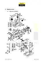
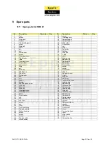
9 Spare parts
9.1
Spare parts list SBS 32
No.
Description
Dimension
Qty.
Nr.
Description
Dimens.
Qty.
1
foot
51
screw
2
screw
52
Clamping lever
3
Gear rack
53
Supporting bar
4
Column
54
Supporting bar
5
Table setting gear
55
Motor plate
6
crank
56
Flat washer
7
Stud bolt
57
nut
8
shaft
58
Motor
9
pin
59
Belt pulley
10
nut
60
Drift key
11
Flat washer
61
Stud bolt
12
screw
62
v-belt
13
Clamping screw
63
shaft
14
Table boom
64
Locking ring
15
table
65
Ball bearing
16
Clamping screw
66
Rubber disc
17
Gear wheel
67
Belt pulley
18
Worm wear
68
Flat washer
19
Ring
69
screw
20
pin
70
screw
21
Stud bolt
71
Flat washer
22
Shaft spline
72
handle
23
Scale ring
73
Belt guard cover
24
Flat washer
74
V-belt
25
hub
75
Ring nut
26
Arm
76
Belt pulley
27
handle
77
Intermediate piece
28
Nonius
78
Locking ring
29
Knurled thumb screw
79
Ball bearing
30
Stud bolt
80
Distance ring
31
Allen key
3
81
Ball bearing
32
Allen key
5
82
Locking ring
33
Clamping screw
83
Ring nut
34
Clamping screw
84
Thrust bearing
35
Screw
85
Ball bearing
36
Flash washer
86
Rubber disc
37
nut
87
Center sleeve
38
nut
88
Ball bearing
39
Set screw
89
spindle
40
screw
90
Reduction sleeve
41
nut
91
chucks
42
cover
92
Chucks key
43
Torsional spring
93
Flat washer
44
Spring housing
94
screw
45
Swtich housing
95
Connection lines
46
screw
96
cover
47
screw
97
Motor cable
48
screw
98
button
49
Tension relief
99
Connection line
50
Head housing


