Page 19
EPS Stromversorgung GmbH
Alter Postweg 101 • 86159 Augsburg
Germany
Fon: +49 821 / 570451-0
Fax: +49 821 / 570451-25
ELR 9000 Series
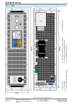
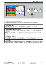
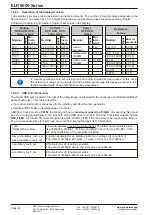
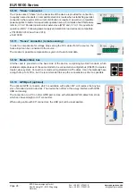
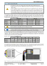
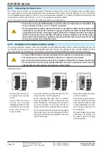
Figure 6 - Control Panel
Overview of the elements of the operating panel
For a detailed description see section
„1.9.6. The control panel (HMI)“
(1)
Touchscreen display
Used for selection of set values, menus, conditions and display of actual values and status.
The touchscreen can be operated with the fingers or with a stylus.
(2)
Rotary knob with push button function
Left knob (turn): adjusting the voltage, power or resistance set values, or setting the parameter values in
the menu.
Left knob (push): selection of the decimal position to be changed (cursor) in the current value selection.
Right knob (turn): adjusting the current set value, or setting parameter values in the menu.
Right knob (push): selection of the decimal position to be changed (cursor) in the current value selection.
(3)
On/Off Button for DC input
Used to toggle the DC input between on and off, also used to start a function run. The LEDs “On” and “Off”
indicate the state of the DC input, no matter if the device is manually controlled or remotely
(4)
USB-A port
For the connection of standard USB sticks up to 32GB, formatted to FAT32. Value tables for the function
generator (UI and IU functions) may be loaded or 100 arbitrary function sequences can be loaded or saved.

