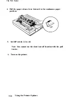


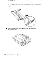

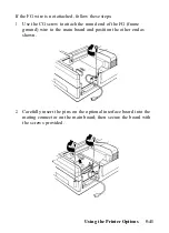
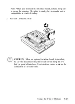


3.
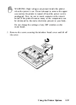
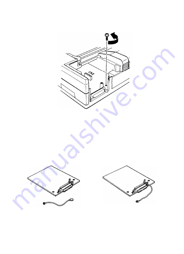
Remove the screw labeled CG from the main board.
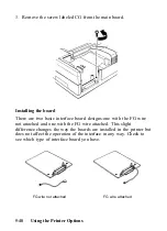
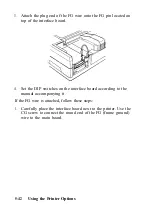
Installing the board
There are two basic interface board designs-one with the FG wire
not attached and one with the FG wire attached. This slight
difference changes the way the boards are installed in the printer but
does not affect the operation of the interface in any way. Check to
see which type of interface board you have.
FG wire not attached
FG wire attached
5-40
Using the Printer Options
Summary of Contents for 1010
Page 1: ......
Page 2: ...EPSON LQ 510 1010 User s Manual ...
Page 182: ...Chapter 7 Troubleshooting Printing 7 2 Paper Handling 7 7 Options 7 10 Troubleshooting 7 1 ...
Page 249: ...Appendix Proportional Width Table A 2 Character Sets A 6 A 1 ...
Page 257: ...PC 865 Norway CODE 0 1 2 3 4 5 6 7 8 9 A B C D E F 0 1 2 3 4 5 6 7 8 9 A B C D E F A 9 ...
Page 271: ......
Page 274: ......
Page 275: ......
Page 276: ......
Page 278: ......
Page 279: ......


