EPSON Stylus PHOTO 2100/2200
Revision B
DISASSEMBLY AND ASSEMBLY
Disassembly
129
4.2.2.3 Removing the Main Board
1.
Remove the Board Unit. (Refer to 4.2.2.2.)
2.
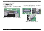
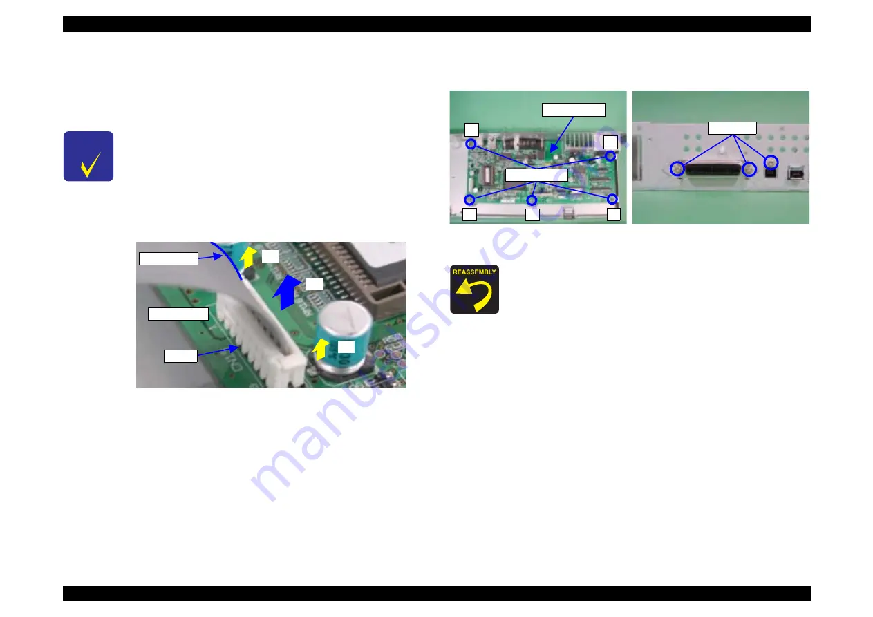
Disconnect the Connector Cable from CN15 of the Main Board.
3.
Remove the five screws 6) C.B.S 3
×
6 (9
±
1kgf.cm) and three screws 7) C.P 3
×
6
(6
±
1kgf.cm) that secure the Main Board, and remove the Main Board.
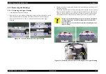
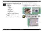
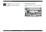
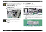
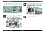
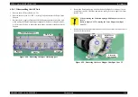
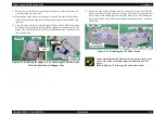
Figure 4-18. Screws That Secure the Main Board
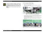
C H E C K
P O I N T
"
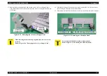
CN15 has a connector cable lock mechanism. Therefore, before
disconnecting the Connector Cable, make sure that the lock
mechanism has been cleared. When reconnecting the cable,
insert the pins correctly into the corresponding ports of CN15.
Refer to Figure 4-17, "Connector Cable Lock Mechanism".
"
Mount the pin side, where a blue line is drawn on the Connector
Cable, to the 1 pin side.
Refer to Figure 4-17, "Connector Cable Lock Mechanism".
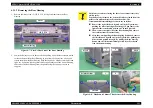
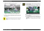
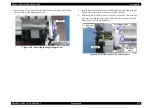
Figure 4-17. Connector Cable Lock Mechanism
1
2
1
CN15
1 pin side
Blue line
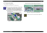
Fit the screws 6) C.B.S 3
×
6 in the order shown in Figure 4-18.
1
3
4
5
2
Main Board
C.B.S 3
×
6
C.P 3
×
6
Summary of Contents for 2200 - Stylus Photo Color Inkjet Printer
Page 1: ...EPSONStylusPHOTO2100 2200 Color Inkjet Printer SEIJ01 016 SERVICE MANUAL ...
Page 8: ...C H A P T E R 1 PRODUCTIONDESCRIPTION ...
Page 39: ...C H A P T E R 2 OPERATINGPRINCIPLES ...
Page 69: ...C H A P T E R 3 TROUBLESHOOTING ...
Page 115: ...C H A P T E R 4 DISASSEMBLYANDASSEMBLY ...
Page 187: ...C H A P T E R 5 ADJUSTMENT ...
Page 214: ...C H A P T E R 6 MAINTENANCE ...
Page 226: ...C H A P T E R 7 APPENDIX ...
Page 254: ......
Page 255: ......
Page 256: ......
Page 257: ......
Page 258: ......


