


Epson Stylus Photo R280/R285/R290/Epson Artisan 50/Epson Stylus Photo T50/T59/T60/P50
Revision C
Chapter 4 Disassembly/Assembly
4.4.17 Front Paper Guide Assy (Disassembling the Printer Mechanism)
96
Confidential
4.4.17 Front Paper Guide Assy
Parts/Components need to be removed in advance
Printer Cover / Paper Support Assy / Upper Housing / Main Board Unit / Panel Assy /
Cover Open Sensor / Printer Mechanism / Ink System / CR Motor / PF Encoder / PF
Scale / PF Motor / EJ Frame Assy / APG Unit / CR Unit / ASF Unit / Upper Paper
Guide
Removal procedure
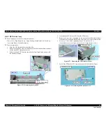
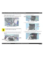
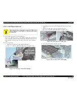
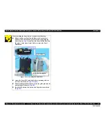
1.
Remove the screw and remove the Parallelism Bushing L.
•
Screw
: C.B.S.(P2) M3x8 (tightening torque: 6-8 kgf.cm)
(No.9)
Figure 4-107. Removing the Parallelism Bushing L
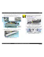
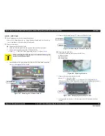
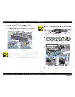
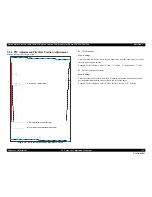
2.
Disconnect the connector of the PE Sensor Cable on the rear side of the
printer.
3.
Remove the screw that secures the Front Paper Guide Assy.
•
Screw
: C.B.S. M3x6 (tightening torque: 7-9 kgf.cm)
(No.1)
Figure 4-108. Removing the PE Sensor Cable
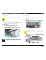
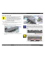
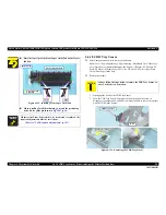
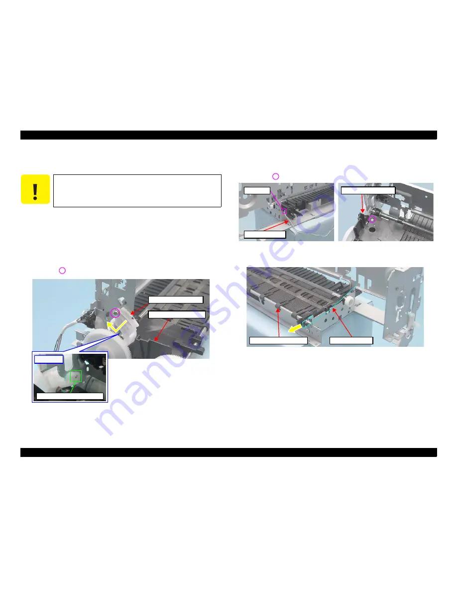
4.
Pull out the EJ Ground Spring to the front side.
Figure 4-109. Removing the EJ Ground Spring
C A U T I O N
Do not touch the surface of the rubber roller of the EJ Roller Assy
and the coated part of the PF Roller Assy as it can adversely affect
the print quality.
Parallelism Bushing L
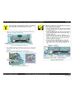
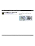
Front Paper Guide Assy
[Rear Side]
Positioning Hole and Guide Pin
PE Sensor Cable
Connector
Front Paper Guide Assy
Front Paper Guide Assy
EJ Ground Spring
Summary of Contents for 50 - Artisan 50 - Printer
Page 8: ...Confidential C H A P T E R 1 PRODUCTDESCRIPTION ...
Page 22: ...Confidential C H A P T E R 2 OPERATINGPRINCIPLES ...
Page 29: ...Confidential C H A P T E R 3 TROUBLESHOOTING ...
Page 52: ...Confidential C H A P T E R 4 DISASSEMBLY ASSEMBLY ...
Page 103: ...Confidential C H A P T E R 5 ADJUSTMENT ...
Page 120: ...Confidential C H A P T E R 6 MAINTENANCE ...


