background image

EPSON  EPL-5700L/5700i

Monochrome Page Printer

SEPG99007

®


Summary of Contents for 5700i - EPL B/W Laser Printer

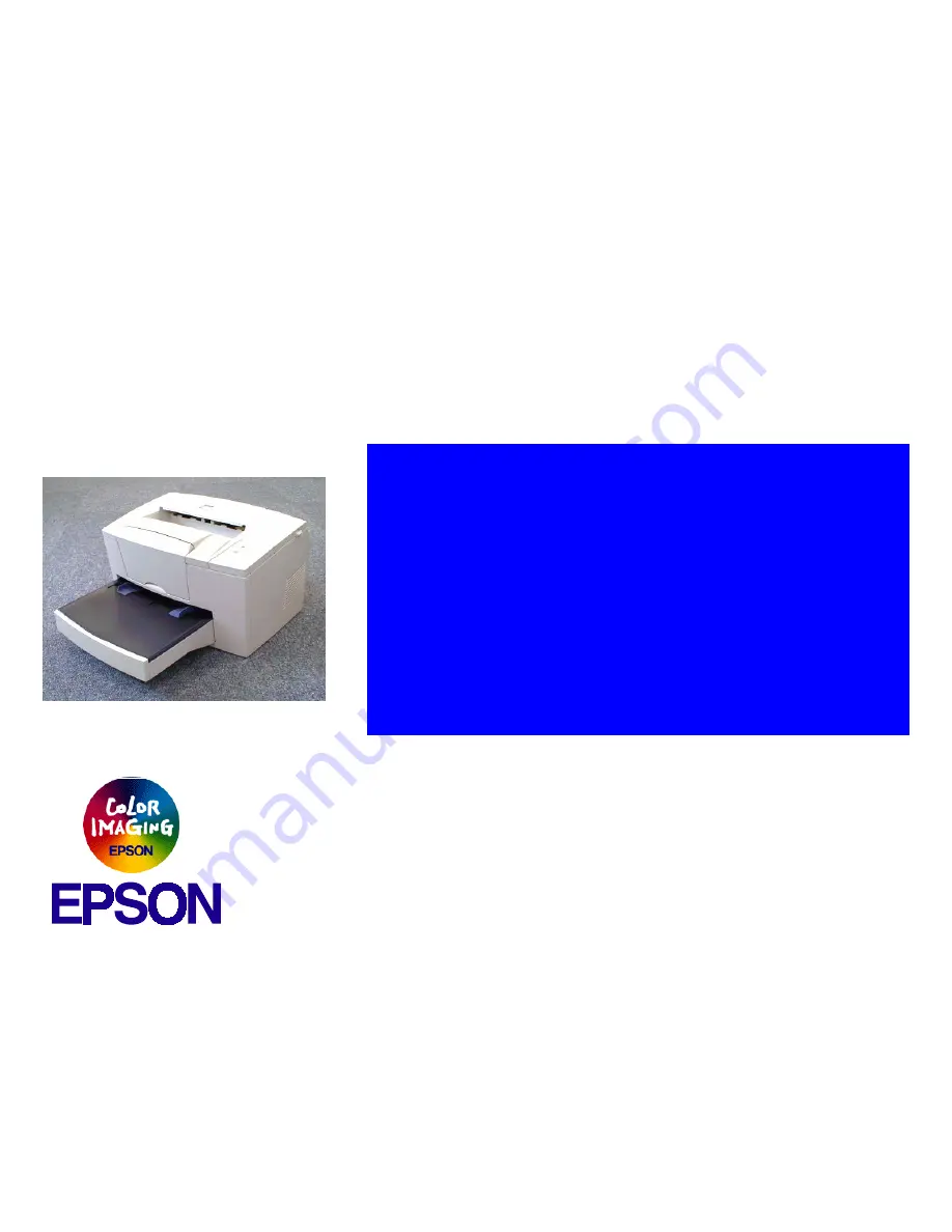
Page 1: ...EPSON EPL 5700L 5700i Monochrome Page Printer SEPG99007 ...

Page 2: ...e contents of this manual However should any errors be detected SEIKO EPSON would greatly appreciate being informed of them The above not withstanding SEIKO EPSON CORPORATION can assume no responsibility for any errors in this manual or the consequences thereof EPSON is a registered trademark of SEIKO EPSON CORPORATION General Notice Other product names used herein are for identification purpose o...

Page 3: ...DO NOT CONNECT THE UNIT TO A POWER SOURCE UNTIL INSTRUCTED TO DO SO WHEN THE POWER SUPPLY CABLE MUST BE CONNECTED USE EXTREME CAUTION IN WORKING ON POWER SUPPLY AND OTHER ELECTRONIC COMPONENTS WARNING 1 REPAIRS ON EPSON PRODUCT SHOULD BE PERFORMED ONLY BY AN EPSON CERTIFIED REPAIR TECHNICIAN 2 MAKE CERTAIN THAT THE SOURCE VOLTAGES IS THE SAME AS THE RATED VOLTAGE LISTED ON THE SERIAL NUMBER RATING...

Page 4: ...scribes the theory of electrical and mechanical operations of the product CHAPTER 3 TROUBLESHOOTING Provides the step by step procedures for troubleshooting CHAPTER 4 DISASSEMBLY AND ASSEMBLY Describes the step by step procedures for disassembling and assembling the product CHAPTER 5 ADJUSTMENTS Provides Epson approved methods for adjustment CHAPTER 6 MAINTENANCE Provides preventive maintenance pr...

Page 5: ...Revision Status Revision Issued Date Description A September 2 1999 First Release ...

Page 6: ...ciples of Controller 22 TROUBLESHOOTING OVERVIEW 26 Overview 26 Electric Check Point 26 HANDLING SERVICE CALL ERRORS 27 Service Call Error Conditions 27 Error LED Lamp 27 Error Code Display and Remedies 27 DISASSEMBLY AND ASSEMBLY OVERVIEW 30 DISASSEMBLY AND ASSEMBLY 31 Control Panel Removal 31 Top Cover Removal 31 Main Control Board Removal 33 ADJUSTMENTS MAINTENANCE APPENDIX CONNECTOR PIN ASSIGN...

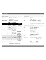
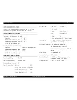
Page 7: ... PRODUCTDESCRIPTION ...

Page 8: ...al time by the expansion circuit and transferred to the engine Speed is enhanced by compressed data expansion hardware The following functions can be upgraded and speed can be increased by RAM SIMM expansion Enhanced MicroGray printing Receive buffer capacity Printing speed RESTRICTIONS DIFFERENCES WITH EPL 5700 1 A network I F including external attachment cannot be used 2 Fonts are not installed...

Page 9: ...imum of 13 MB is valid 15 When using parallel connection printing is not possible if bi directional communication is hindered by the following conditions There is a printer selecting switch between the PC and the printer for parallel connection Old PC that does not support bi directional communication is used Unspecified cables are used 16 If there is no paper in the MP tray the paper size will be...

Page 10: ...nductor Charge Rotating Brush Charging Type Developer Exposed Section Developer System Toner Mono component Nonmagnetic Toner Transfer M ethod Roller Transfer Fixing Heat Roller System Density Regulator Developer Bias Variation System can be regulated by user Resolution 600 dpi PRINTING SPEED Printing Speed 8 ppm A4 B5 A5 Vertical Feed First Print 19 seconds A4 Vertical Feed 18 2 seconds B5 17 3 s...

Page 11: ... Slot 1 32MB 16MB 8MB 4M B EDO A maxim um of 13MB is valid ROM Program 512Kbytes Host Interface Standard Centronics Bi directional Parallel IEEE 1284 nibble ECP com pliant USB Serial No slot for the optional I F Table 1 1 Paper Handling Paper Supply Capacity Paper Size Permissible Paper Thickness Multipurpose Tray 150 sheets 76 2 x 127 to 215 9 x 355 6mm 60 to 90g m2 16 to 24lb 50 sheets Japanese ...

Page 12: ... SPECIFICATIONS Power Supply Voltage 100 10 Power Supply Frequency 50 to 60Hz 3Hz Standard M aximum Current 6 3A Power Consumption Maximum 580W Average during continuous printing 200W Standby Mode Heater On 490W Standby Mode Heater Off 15W AC Line Noise Pulse W idth 50 to 1 000ns Pulse Polarity Repeat Non simultaneous Mode Comm on Norm al Voltage 1KV Parts can withstand up to 2KV without dam age I...

Page 13: ...printed pages or five years whichever comes first MPBF 25 000 sheets or more MTBF 3 000 hours 10 m onths or m ore Paper Feed Reliability when using the recomm ended paper under norm al conditions Jam Rate 1 2000 or less not including multiple pages Misfeed 1 2000 or less Multiple Page Feed Rate 1 500 or less Paper W rinkling 1 1000 or less Paper Leading Edge Folds 1 1000 or less corner folds more ...

Page 14: ...ordance with OSHA Ozone Emissions Conforms to UL 478 5th version Materials Conforms to Swiss environmental protection laws does not include CdS Ozone 0 02 ppm or less Potential Toxicity OPC toner and plastic parts are nontoxic Noise Stand by 30 dB A or less In operation 47 0 dB A or less Table 1 2 Safety Standards Model Name Applicable Certification 120V Model UL 1950 CSA 22 2 No 950 200V Model TÜ...

Page 15: ...ch has been used with a thermal transfer or ink jet printer Paper which is too thick or too thin Wet damp paper Paper to which a special coating has been applied or colored paper which has gone through surface processing Paper whose surface is too smooth or too rough or paper whose texture is different on the front and back Paper with holes for binders or perforations Folded curled or damaged pape...

Page 16: ...Feed Slot Optional Lower Cassette Normal Paper A4 210 x 297 A5 148 x 210 JIS B5 182 x 257 Letter 8 5 x 11 Half Letter 5 5 x 8 5 Legal 8 5 x 14 EXE 7 25 x 10 5 Government Legal 8 5 x 13 Government Letter 8 x 10 5 F4 210 x 330 Special Paper Postcard 100 x 148 Monarch 98 43 x 190 5 C10 104 78 x 241 3 DL 110 x 220 C5 162 x 229 C6 114 x 162 International B5 176 x 250 ...

Page 17: ... Figure 1 2 Control Panel FLASHING LED Table 1 7 LED Lamps Name Color 1 Ready Lamp Green 2 Error Lamp Red 1 2 Table 1 8 Meaning of Flashing LED Lamps Ready Lamps Error Lamp Meaning OFF OFF Power OFF ON OFF Possible to print Flashing OFF Warming up receiving data OFF Flashing Recoverable error including paper out OFF ON Service call error C H E C K P O I N T Since the EPL 5700L 5700i is a host base...

Page 18: ...shown below However this does not include images with extrem ely poor com pression ratio Table 1 9 Recommended RAM Capacity No RAM Expansion MicroGray printing may not be possible at 600 dpi For a host with slow transfer speed normal 600 dpi printing may not be possible 4MB Expansion Printing is possible under all conditions C A U T I O N The memory shown below cannot be used with the EPL 5700L 57...

Page 19: ...700i Revision A PRODUCT DESCRIPTION OPTIONS AND CONSUMABLE PRODUCTS 19 1 6 OPTIONS AND CONSUMABLE PRODUCTS Optional lower cassette unit and printer cables for EPL 5700L 5700i are the sam e as options for EPL 5700 ...

Page 20: ... OPERATINGPRINCIPLES ...

Page 21: ...ES OPERATING PRINCIPLES OF MECHANISM 21 2 1 OPERATING PRINCIPLES OF MECHANISM The EPL 5700L 5700i adopts the same m echanism as used in the previous model Refer to the EPL 5700 Service Manual for the detailed operating principles of each mechanism ...

Page 22: ...gnal The Engine Controller receives video signal from the M ain Controller and drives the engine to print FUNCTIONS OF THE MAIN CONTROLLER Communication with the host computer receiving print data and sending status Processing the print data analyzing comm and and generating video signal Sending the video signal to the Engine Controller Monitoring panel or switch conditions FUNCTIONS OF THE ENGINE...

Page 23: ... 3 3V Serial EEPROM 1kb IC8 Reset Signal SLC 208pin 5 3 3V E05B68NA IC5 22 9982MHz MCLKIN MCLKOX 22 9982MHz 22 9982MHz A23 1 CPU TM95C001 64pin IC1 16 ROM 4Mb 16 40pin IC2 DRAM 16Mb 16 42pin IC3 MA10 0 16 D15 0 CN1 TSUB 64pin 5 3 3V E05B69NA IC21 16 16 CN5 RAMSIMM 72pin USB 4pin 48MHz CN2 LV161284 48pin IC7 3 3V Parallel 36pin Engine Controller CN3 ...

Page 24: ...05B69NA IC21 Controls USB I F Package 64 pin QFP Power supply voltage 5V 3 3V Operation frequency max 48MHz TTL SN74LV162184DGGR IC7 1284 driver Receives sends parallel I F signal Power supply voltage 5V DRAM M5M418165CJ 6 IC3 One EDO with 16Mb 16bit 60ns is mounted Operates as standard memory ROM HN27C4000G 10 IC2 4Mb 16bit and 40pin module Stores the control program RAMSIMM CN1 72 pin memory exp...

Page 25: ... TROUBLESHOOTING ...

Page 26: ...r occurs EPSON Printer W indow 3 appears on the host screen as a pop up window which provides detailed instructions on how to handle each error Most of the errors will be cleared by following the instructions of the pop up window Also refer to the section Troubleshooting of the EPL 5700L 5700i User s Guide which gives instructions for solving general problem s 3 1 2 Electric Check Point Refer to 3...

Page 27: ...ration check the Service Call Error Code and take appropriate measures as shown in Table 3 1 SERVICE CALL ERROR CODE DISPLAY If a Service Call Error occurs and EPSON Printer W indow 3 pops up on the screen press Ctrl Shift Enter together to display the error code C A U T I O N This function should not be made open to users Table 3 1 Service Call Error Codes Service Call Error Code Error Descriptio...

Page 28: ...ies or Document Defaults for Windows NT4 0 and select Optional Settings 2 Click the left button of the mouse while pressing ALT CTRL SHIFT W and the dialogue box shown below will appear Figure 3 1 Reset the EEPROM 3 Click OK and EEPROM will be reset C A U T I O N The above function should not be made open to users Cancel ...

Page 29: ... DISASSEMBLYANDASSEMBLY ...

Page 30: ...erent from those of EPL 5700 Control Panel Top cover securing m ethod Main Board USB I F The other mechanism and exterior parts are exactly the sam e as used in EPL 5700 Therefore this chapter contains the disassembly and assembly procedures only for the parts and units mentioned above Refer to the EPL 5700 Service Manual for other items ...

Page 31: ...rinter Refer to the EPL 5700 Service M anual pp 4 10 for the Control Panel disassem bly and assem bly procedures Figure 4 1 Control Panel Removal No 1 Figure 4 2 Control Panel Removal No 2 4 2 2 Top Cover Removal 1 Remove the right cover See section 4 2 2 of the EPL 5700 Service Manual 2 Remove the control panel See section 4 2 1 of this manual 3 Remove the front cover See section 4 2 7 of the EPL...

Page 32: ...8 and a plate located on the upper part of the shield cover of the Main Control Board see Figure 4 3 below Figure 4 3 Plate Removal 6 Push both left and right hinges of the top cover outward as shown in Figure 4 4 and remove the top cover Figure 4 4 Top Cover Removal Screw CS M3X8 Plate Hinges Top Cover ...

Page 33: ...ld cover of the Main Control Board and remove the shield cover See section 4 2 9 of the EPL 5700 Service Manual 5 Remove the harnesses which are connected to the connector on the Main Control Board 6 Remove 10 screws CS M3x8 securing the Main Control Board on the printer See section 4 2 9 of the EPL 5700 Service Manual 7 Remove a fixing screw for USB interface CS M3x6 and two fixing screws for par...

Page 34: ... ADJUSTMENTS ...

Page 35: ...EPL 5700L 5700i Revision A ADJUSTMENTS 35 Refer to the EPL 5700 Service Manual Chapter 5 for adjustment procedures ...

Page 36: ... MAINTENANCE ...

Page 37: ...EPL 5700L 5700i Revision A MAINTENANCE 37 Refer to the EPL 5700 Service Manual Chapter 6 for maintenance procedures ...

Page 38: ... APPENDIX ...

Page 39: ...aper Empty Sensor Heater Lamp Interlock Switch Lower Cassette Table 7 1 Connector List Board Connector Function Reference C292 MAIN CN1 For Expanded RAMSIMM 72 pin EPL 5700 Service Manual Table 7 5 and 7 7 CN2 Parallel Interface 36 pin EPL 5700 Service Manual Table 7 8 CN3 Video not used CN4 Control Panel LED Control CN5 USB Interface Table 7 2 CN202 Fusing Thermister CN203 Paper Feed Solenoid Con...

Page 40: ...0i Revision A APPENDIX CONNECTOR PIN ASSIGNMENTS 40 Table 7 2 Connector CN5 Pin No Signal Name Direction Function 1 POWER Cable Power Supply 2 D Bi directional Data Signal 3 D Bi directional Data Signal 4 GND Ground ...

Page 41: ...EPL 5700L 5700i Revision A APPENDIX CIRCUIT BOARD COMPONENT LAYOUT 41 7 2 CIRCUIT BOARD COMPONENT LAYOUT Figure 7 2 C292 Main Control Board Component Layout ...

Page 42: ...ploded Diagrams Refer to the EPL 5700 Service Manual 7 3 Exploded Diagram as the exterior and m echanism of the EPL 5700L 5700i are basically the same The only difference with the previous m odel is PLATE which has been newly added to 6 FRAM ES I and its exploded diagram s are shown on the following pages ...

Page 43: ...EPL 5700L 5700i Revision A APPENDIX EXPLODED DIAGRAMS ASP LIST 43 ...

Page 44: ...EPL 5700L 5700i Revision A APPENDIX EXPLODED DIAGRAMS ASP LIST 44 ...

Page 45: ...EPL 5700L 5700i Revision A APPENDIX EXPLODED DIAGRAMS ASP LIST 45 ...

Page 46: ...EPL 5700L 5700i Revision A APPENDIX EXPLODED DIAGRAMS ASP LIST 46 ...

Page 47: ...EPL 5700L 5700i Revision A APPENDIX EXPLODED DIAGRAMS ASP LIST 47 ...

Page 48: ...EPL 5700L 5700i Revision A APPENDIX EXPLODED DIAGRAMS ASP LIST 48 ...

Page 49: ...EPL 5700L 5700i Revision A APPENDIX EXPLODED DIAGRAMS ASP LIST 49 ...

Page 50: ... GUIDE 2 02 1048622 ROLLER 2 03 1048624 GUIDE LEVER 2 04 1040706 GEAR ASSY 2 05 1040709 TORSION SPRING 2 06 1040710 COVER 2 07 1040711 ROCK LEVER 2 08 1040712 PLATE 3 01 1021636 BUSHING 3 02 1040714 CAM 3 03 1040715 ROLL 3 04 1048613 ROLLER 3 05 1040717 ROLLER 3 06 1040718 HOLDER 3 07 1040719 PRESSURE SPRING 3 08 1040720 JOINT 3 09 1048612 BUSHING 3 10 1040722 GEAR 18T 3 11 1048614 SHAFT 3 12 1040...

Page 51: ...620 GUIDE 4 21 1040815 SHEET 4 22 1048615 HOUSING ASSY 4 23 2028489 FUSING UNIT 120V Table 7 3 Parts List continued Diagram No Parts Code Parts Name 4 28 1048616 HOLDER L 4 29 1048617 HOLDER R 4 30 1048618 STOPPER L 4 31 1048619 STOPPER R 4 32 1013954 SEPARATOR ROLL 5 01 1048630 FRAME 5 04 2027740 MOTOR M1 5 05 1040738 GEAR 40T 5 06 1040739 GEAR 18 50T 5 07 1040740 GEAR 20 44T 5 08 1040741 GEAR 20...

Page 52: ...ESS 6 03 2027750 SWITCH PE1 6 04 1040771 BRACKET 6 05 1040772 HOLDER Table 7 3 Parts List continued Diagram No Parts Code Parts Name 6 06 1048621 RUBBER FOOT 6 07 1040775 PORYESTER FILM 6 08 1040776 GUIDE PLATE 6 09 2027751 HARNESS 6 10 2032079 SWITCH 6 12 1031615 SHOULDER SCREW 6 13 2027754 HARNESS 6 15 1040779 COVER 6 16 1040780 BRACKET 6 17 1040782 GROUND PLATE 6 18 1040783 COVER 6 19 1040784 P...

Page 53: ...10 1048627 HOLDER 7 11 1013911 GEAR 14T 7 12 2027759 PRINT HEAD UNIT 7 13 1040794 HOLDER 7 14 1040795 TORSION SPRING 7 15 1040796 WIRING SADDLE 18 5 7 16 1015333 EDGE COVER 8 5H 7 17 1004683 EDGE COVER 15H Table 7 3 Parts List continued Diagram No Parts Code Parts Name ...

Page 54: ...EPL 5700L 5700i Revision A APPENDIX CIRCUIT DIAGRAM 54 7 4 CIRCUIT DIAGRAM Circuit diagrams of the Main Control Board is shown on the following pages ...

Page 55: ......

Page 56: ......

Reviews: