


ELPMBUNI
Page - 4 -
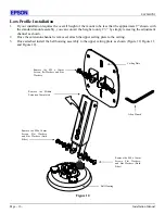
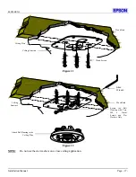
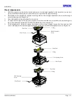
Installation Manual
Warning Statements
WARNING
:
PREMIER MOUNTS DOES NOT WARRANT AGAINST DAMAGE CAUSED BY THE
USE OF ANY PREMIER MOUNTS PRODUCT FOR PURPOSES OTHER THAN
THOSE FOR WHICH IT WAS DESIGNED OR DAMAGE CAUSED BY
UNAUTHORIZED ATTACHMENTS OR MODIFICATIONS, AND IS NOT
RESPONSIBLE FOR ANY DAMAGES, CLAIMS, DEMANDS, SUITS, ACTIONS OR
CAUSES OF ACTION OF WHATEVER KIND RESULTING FROM, ARISING OUT OF
OR IN ANY MANNER RELATING TO ANY SUCH USE, ATTACHMENTS OR
MODIFICATIONS.
WARNING:
THE CEILING STRUCTURE MUST BE CAPABLE OF SUPPORTING A MAX
WEIGHT OF 25 LBS., THE WEIGHT OF THE PROJECTOR. IF NOT, THE CEILING
MUST BE REINFORCED. PROPER INSTALLATION PROCEDURE BY QUALIFIED
PERSONNEL AS OUTLINED IN THE INSTALLATIONS INSTRUCTIONS MUST BE
ADHERED TO. FAILURE TO DO SO COULD RESULT IN SERIOUS PERSONAL
INJURY.
WARNING:
SAFETY MEASURES MUST BE PRACTICED AT ALL TIMES DURING THE
INSTALLATION OF THIS PRODUCT. USE PROPER SAFETY GEAR AND TOOLS
FOR THE INSTALLATION PROCEDURE TO PREVENT PERSONAL INJURY.
WARNING:
PRIOR TO THE INSTALLATION OF THIS PRODUCT, THE INSTALLATION
INSTRUCTIONS SHOULD BE READ AND COMPLETELY UNDERSTOOD. THE
INSTALLATION INSTRUCTIONS MUST BE READ TO PREVENT PERSONAL
INJURY AND PROPERTY DAMAGE. KEEP THESE INSTALLATION
INSTRUCTIONS IN AN EASILY ACCESSIBLE LOCATION FOR FUTURE
REFERENCE.
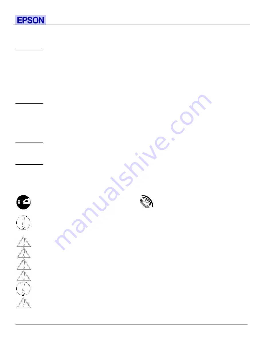
Indicates that the power plug is to be
disconnected from the power outlet.
Contact Premier Mounts with any
questions – (800) 368-9700.
Safety precautions must be taken at all times.
Warning and Caution statements.
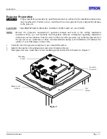
A secure structure must support the weight, or load, of the projector. When mounting to a ceiling that contains wooden
studs, dead center of the wooden stud must be confirmed prior to installation.
Do not install on a structure that is prone to vibration, movement or chance of impact. Failure to do so could result in
damage to the projector and/or damage to the mounting surface.
Do not install near heater, fireplace, direct sunlight, air conditioning or any other source of direct heat energy. Failure to
do so may result in damage to the projector and could increase the risk of fire.
At least two qualified people should perform the installation procedure. Injury and/or damage can result from dropping or
mishandling the projector.
Recommended mounting surfaces: wooden studs, solid-flat concrete, and reinforced metal studs. If the mount is to be
installed on any surface other than wooden studs, use suitable hardware (which is commercially available).