EPSON Stylus PHOTO 895/785EPX
Revision A
Operating Principles
Electrical Circuit Operating Principles
45
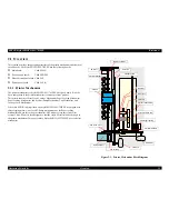
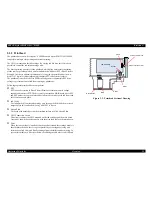
2.2.1.2 Protection circuit
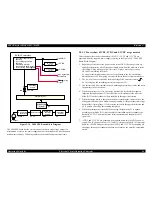
The C408 PSE board has the various control circuits to stop voltage output if a
malfunction occurs on the power supply board or the main board or while the printer
mechanism is on duty. Following explains each control and protection circuit.
+42VDC line constant voltage control circuit:
The output of +42V line is monitored by the ZC-RCC converter detection circuit.
This circuit prevents voltage drop so that the output voltage can be held at a
constant level.
+42V line over current protection circuit:
The output voltage extremely drops when the +42V line becomes the over current
condition. The ZC-RCC converter feeds back the occurrence of over voltage to the
primary side via the same IC if it detects the voltage drop in the 42V line. The
primary side stops switching and protects the printer electric circuit and
mechanism. Reset is automatically performed.
+42V line over voltage protection circuit:
If the +42V line exceeds 58V, the ZC-RCC converter detects the over voltage and
feeds back the occurrence of over voltage to the primary side via the same IC. The
primary side stops switching and protects the printer electric circuit and
mechanism.
+5VDC, +3.3VDC line constant voltage/current control circuit:
+The +5V and +3.3V line output currents and output voltage are monitored by the
self-excited down chopper circuit (IC51, IC151). The monitor information is input
to the internal comparator and stabilization circuit in IC. The self-excited down
chopper circuit (IC51, IC151) stops the output if the over current is detected.
+5V, +3.3V line over current protection circuit:
The ZC-RCC converter feeds back the occurrence of over voltage to the primary
side via the same IC when the +5V or +3.3V line becomes the over current
condition. The primary side stops switching and protects the printer electric circuit
and mechanism. It is possible to reset only by turning on the power again.
+5V, +3.3V line over voltage protection circuit:
If the +42V line exceeds 9V, the ZC-RCC converter detects the over voltage and
feeds back the occurrence of over voltage to the primary side via the same IC. The
primary side stops switching and protects the printer electric circuit and
mechanism.
2.2.1.3 PS Control Function
This power supply circuit enables to supply the voltage to the 5V, 3.3V and 42V lines
for about 30 seconds by using the secondary power supply even if the power is turned
off with the power switch on the operation panel. This procedure ensures the following
operation even if the printer's power switch is turned off while printing.
When the CR unit is not at the home position while the printer is printing, the
CR unit stops printing, then the power is shut down after returning to the
home position and finishing the locking action.
When the papers are stored in the printer mechanism in the condition supplied
by the ASF even if the printer is not printing, the paper is ejected and then the
power is shut down.
2.2.1.4 Power saving mode
The power supply circuit activates the power saving mode by the signal ESAVE from
the control circuit. The +42V line repeats rise/fall in the power saving mode.

