background image

EPSON Stylus PHOTO 895/785EPX

Revision A

Disassembly and Assembly

Overview

71

4.1.3  Work Completion Check

If any service is made to the printer, use the checklist shown below to confirm all 
works are completed properly and the printer is ready to be returned to the user.

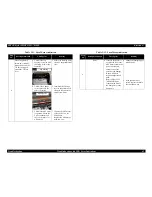
Table 4-2.  Completion Check

Classifi-

cation

Item

Check Point

Status

Main Unit

Self-test

Is the operation normal?

†

Checked 

†

Not necessary

On-line Test

Is the printing successful?

†

Checked 

†

Not necessary

Printhead

Is ink discharged normally from 
all the nozzles?

†

Checked 

†

Not necessary

Carriage 
Mechanism

Does it move smoothly?

†

Checked 

†

Not necessary

Is there any abnormal noise 
during its operation?

†

Checked 

†

Not necessary

Is there any dirt or foreign 
objects on the CR Guide Shaft?

†

Checked 

†

Not necessary

Is the CR Motor at the correct 
temperature?
(Not too heated?)

†

Checked 

†

Not necessary

Paper Feeding 
Mechanism

• Is paper advanced smoothly?

• No paper jamming?

• No paper skew?

• No multiple feeding?

• No abnormal noise?

†

Checked 

†

Not necessary

Is the PF Motor at correct 
temperature?

†

Checked 

†

Not necessary

Is the ASF motor at correct 
temperature?

†

Checked 

†

Not necessary

Is the paper path free of any 
obstructions?

†

Checked 

†

Not necessary

Adjustment

Specified 
Adjustment

Are all the adjustment done 
correctly?

†

Checked 

†

Not necessary

Lubrication

Specified 
Lubrication

Are all the lubrication made at 
the specified points?

†

Checked 

†

Not necessary

Is the amount of lubrication 
correct?

†

Checked 

†

Not necessary

Function

Printer
Firmware version

Version:

†

Checked 

†

Not necessary

Printon
Firmware version

Version:

†

Checked 

†

Not necessary

Packing

Ink Cartridge

Are the ink cartridges installed 
correctly?

†

Checked 

†

Not necessary

Protective 
Materials

Have all relevant protective 
materials been attached to the 
printer?

†

Checked 

†

Not necessary

Others

Attachments, 
Accessories

Have all the relevant items been 
included in the package?

†

Checked 

†

Not necessary

Table 4-2.  Completion Check (continued)

Classifi-

cation

Item

Check Point

Status

Summary of Contents for 785EPX - Stylus Photo Color Inkjet Printer

Page 1: ...EPSON STYLUSPHOTO895 785EPX Color Inkjet Printer SEIJ01001 SERVICE MANUAL Download Free Service Manual and Resetter Printer at http printer1 blogspot com ...

Page 2: ...e the accuracy of the contents of this manual However should any errors be detected SEIKO EPSON would greatly appreciate being informed of them The above not withstanding SEIKO EPSON CORPORATION can assume no responsibility for any errors in this manual or the consequences thereof EPSON is a registered trademark of SEIKO EPSON CORPORATION General Notice Other product names used herein are for iden...

Page 3: ...N WORKING ON POWER SUPPLY AND OTHER ELECTRONIC COMPONENTS 4 WHEN DISASSEMBLING OR ASSEMBLING A PRODUCT MAKE SURE TO WEAR GLOVES TO AVOID INJURIER FROM METAL PARTS WITH SHARP EDGES WARNING 1 REPAIRS ON EPSON PRODUCT SHOULD BE PERFORMED ONLY BY AN EPSON CERTIFIED REPAIR TECHNICIAN 2 MAKE CERTAIN THAT THE SOURCE VOLTAGES IS THE SAME AS THE RATED VOLTAGE LISTED ON THE SERIAL NUMBER RATING PLATE IF THE...

Page 4: ...s Exploded diagram Parts List Symbols Used in this Manual Various symbols are used throughout this manual either to provide additional information on a specific topic or to warn of possible danger present during a procedure or an action Be aware of all symbols when they are used and always read NOTE CAUTION or WARNING messages Indicates an operating or maintenance procedure practice or condition t...

Page 5: ...Revision Status Revision Issued Date Description A April 19 2001 First Release Download Free Service Manual and Resetter Printer at http printer1 blogspot com ...

Page 6: ... Rule 17 1 5 6 3 Date Range 17 1 6 Printer PNL Operation Specifications 18 1 6 1 Switches 18 1 6 2 Indicators 18 1 6 3 Panel Functions 18 1 6 4 Printer Condition and Panel Status 19 1 7 Printer Initialization 20 1 8 Initial setting values 20 1 9 Errors 21 1 10 Printing of filled patterns 21 1 11 Monochrome PNL operation specification 22 1 11 1 Appearance 22 1 11 2 Swith Function 23 1 11 3 Process ...

Page 7: ...al 75 4 2 2 2 Monochrome panel board removal 77 4 2 3 Housing Lower Cover Removal 78 4 2 3 1 Housing Lower Cover Left Removal 78 4 2 3 2 Housing Lower Cover Right Removal 79 4 2 4 Printhead removal 79 4 2 5 CR motor removal 82 4 2 6 Waste drain ink pad unit removal 83 4 2 7 Printer mechanism removal 84 4 2 8 Circuit board removal 85 4 2 9 LD Roller removal 88 4 2 10 HP PE Sensor removal 92 4 2 11 ...

Page 8: ... 5 5 2 Brightness adjustment 134 5 5 2 1 Brightness adjustment procedures 134 5 5 3 Image pattern inspection 135 Chapter 6 Maintenance 6 1 Overview 137 6 1 1 Cleaning 137 6 1 2 Service Maintenance 138 Chapter 7 Appendix 7 1 Connector Summary 146 7 1 1 Major Component Unit 146 7 1 2 EEPROM Address Map printer section 151 7 1 3 EEPROM Address Map Storage section 154 7 2 Exploded Diagram 159 7 3 Part...

Page 9: ...C H A P T E R 1 PRODUCTDESCRIPTION Download Free Service Manual and Resetter Printer at http printer1 blogspot com ...

Page 10: ...ard reader function for PCMCIA Flash ATA Applicable to Compact Flash Smart Media Memory Stick Microdrive with PCMCIA adapter Connected with a printer unit via USB hub High Color Print Quality High Speed Printing Exclusively used for USB I F Windows Macintosh exclusive Compact Space Saving Multi size Compatible ASF Roll paper can be used Preview monitor optional Figure 1 1 External View ...

Page 11: ...or 48 nozzles x 5 Cyan Magenta Yellow Light cyan Light magenta Print Direction Bi direction with logic seeking Print Speed Printable Columns This value is the speed of normal dot printing Control Code ESC P Raster Character Tables One international character sets PC 437 US Standard Europe Typeface Bit map LQ font EPSON Courier 10 CPI Table 1 1 Character Mode Character Pitch Printable Column LQ Spe...

Page 12: ...sis 220 240V Version Rated Voltage AC220V 240V Input Voltage Range AC198 264V Rated Frequency Range 50 60Hz Input Frequency Range 49 5 60 5Hz Rated Current 0 25 A Power Consumption Approx 19W ISO10561 Letter Pattern Approx 3 5W in standby mode Energy Star compliant Insulation Resistance 10M ohms min between AC line and chassis DC 500V Dielectric Strength AC 1500V rms 1 minute between AC line and c...

Page 13: ...e printing 1 2 8 Safety Approvals 120V Version Safety Standards UL1950 CSA22 2 No 950 EMI FCC part 15 subpart B Class B CSA C108 8 Class B 220 240V Version Safety Standards EN60950 VDE EMI EN55022 CISPR Pub 22 Class B AS NZS 3548 Class B 1 2 9 Acoustic Noise Level Approx 47dB A According to ISO 7779 1 2 10 CE Marking 220 240V Version Low Voltage Directive 73 23 EEC EN60950 EMC Directive 89 336 EEC...

Page 14: ...nly Transport Rev 1 0 Storage Bit Rate 12Mbps Full Speed Device Data Encoding NRZI Adaptable Connector USB Series B Recommended Cable Length 2 meters Figure 1 3 USB Pin Assignment Device ID 00H 60H MFG EPSON CMD ESCPL2 BDC D4 MDL Stylus SP Photo SP 785 EPX CLS PRINTER DES EPSON SP Stylus SP Photo SP 785EPX Table 1 3 Connector Pin Assignment and Signals Pin No Signal Name I O Function Description 1...

Page 15: ...Standard 97 JEIDA 1 4 2 Supported Memory Card PCMCIA Flash ATA card Compact Flash with PCMCIA adapter Smart Media with PCMCIA adapter Memory Stick with PCMCIA adapter Microdrive with PCMCIA adapter 1 4 3 Supported Voltage 5v only 3 3v 5v 3 3v only Note1 Media that uses 3 3v 5v is automatically set based on the VS1 terminal PCMCIA Note2 The supply current to the memory card is max 330mA ...

Page 16: ...e that the image sizes that are mandatory for DCF Version 1 0 are as follows Horizontal 160 X 1800 pixel Vertical 160 Y 1200 pixel However this machine handles the following size range Horizontal 160 X 3200 pixel Vertical 160 Y 3200 pixel 1 5 4 Maximum Number of Photo Data Files This machine can handle up to 999 photo data files If 1000 or more photo data files are recorded in a memory card these ...

Page 17: ...standard format Exif 2 Data and time information of the file system supported in DOS timestamp of the file 3 Fixed values 1 January 1970 00 00 00 Note that the date and time information attached to each photo data file may not match with the date and time at which the photo was captured Some of the said date and time data is updated due to a calendar setting whether the function exist not exist in...

Page 18: ...oads or Ejects the Paper Pushing within 3seconds Starts the Cleaning of head Pushing for 3seconds When carriage is on the Ink Cartridge change position return carriage from Ink Cartridge change position Roll paper Loads or Ejects Back Out feed by pushing for 3 seconds the Roll paper Tear Off feed and return When carriage is on the Ink Cartridge change position return carriage from Ink Cartridge ch...

Page 19: ...ch Function Maintenance Initialize EEPROM Roll paper Pushing for 10 seconds Reset the ink overflow counter in the EEPROM Table 1 7 Error LED Indication Printer Status Error LED Priority Power ON 10 Ink sequence proceeding 6 Ink cartridge changing 5 Data processing 9 Paper out On 4 Paper jam condition On 3 Ink end black On Blink 8 Ink low black Blink 8 Ink end color On Blink2 9 Ink low color Blink ...

Page 20: ...ast power off When printer is initialized the following actions are performed a Cap the printer head b Eject a paper c Clears input data buffer d Clears print buffer e Sets default values 3 Software Initialization The ESC command also initialize the printer When printer is initialized the following actions are performed a Clears print buffer b Sets default values 1 8 Initial setting values Initial...

Page 21: ...er out error Paper Jam When the printer fails to eject a sheet it goes into a paper jam error No Ink Cartridge When the printer detects that ink cartridge comes off or failed to read or write CSIC data it goes into this error mode Maintenance Request When the total amount of ink wasted through cleanings and flushing reaches to the limit printer indicates this error and stops In such a case the abs...

Page 22: ...d Figure 1 5 Monochrome PNL of Stylus PHOTO895 Figure 1 6 Monochrome PNL of Stylus PHOTO785 EPX Print Mode Paper Type Paper Size Page Layout Select Photo Copies Quality Photo enhance Select Photo Brightness Processing Cancel Print c c c c g g g g i i i i d d d d e e e e f f f f h h h h Print Mode Paper Type Paper Size Page Layout Select Photo Copies Quality Photo enhance Select Photo Brightness Pr...

Page 23: ...nel Table 1 8 Switch description No Name Description 1 LCD PNL Indicates the print condition setting contents of printer 2 Print Printer start operation 3 Cancel Cancellation of operations and printing action 4 Select Photo Selects one or all frames 5 Cross shaped key Moves the cursor 6 Brightness Sets frame function 7 Processing Lights on or blinks while processing Table 1 9 Error LCD Indication ...

Page 24: ...05mm Japanese Chokei4 90mm x 205mm Japanese Yokei1 120mm x 176mm Japanese Yokei2 114mm x 162mm Japanese Yokei3 98mm x 148mm Japanese Yokei4 105mm x 235mm Quality 10 DL C6 Bond paper PPC Air mail Japanese Chokei3 4 Craft New Kent Japanese Yokei1 2 3 4 Craft New Kent Weight 10 DL C6 45g m2 75g m2 12 lb 20 lb Japanese Chokei3 4 50g m2 70g m2 43 kg 60 kg Japanese Yokei1 2 3 4 50g m2 100g m2 43 kg 86 k...

Page 25: ...279mm A6 105mm x 148mm 4 Photo Quality Glossy Film Size A4 210mm x 297mm Letter 216mm x 279mm Japanese Postcard 100mm x 148mm 5 OHP Sheet Size A4 210mm x 297mm Letter 216mm x 279mm 6 Matte Paper Size A4 210mm x 297mm Letter 216mm x 279mm 7 Label Sheet Size A4 210mm x 297mm Japanese Postcard 100mm x 148mm A6 105mm x 148mm 8 Iron On Cool Peel Transfer Paper Size A4 210mm x 297mm Letter 216mm x 279mm...

Page 26: ...er dimension is defined by using command otherwise it is not reduced 14mm As for an area between 3mm and 14mm margin printing quality may decline Refer to 1 12 2 Paper Specification for PW paper width and PL paper length Printable Area A Printable Area B Printable Area A 14mm Right Margin 3mm Left Margin 3mm Top Margin 3mm Bottom Margin 3mm Table 1 10 Printing Area Paper Size Left Margin min Right...

Page 27: ...ure 1 8 Printable Area for Envelopes Table 1 11 Envelope Margin Size Left Margin min Right Margin min Top Margin min Bottom Margin min 10 3 mm 0 12 28 mm 1 10 3 mm 0 12 14 mm 0 55 DL 3 mm 0 12 7 mm 0 28 3 mm 0 12 14 mm 0 55 C6 3 mm 0 12 3 mm 0 12 3 mm 0 12 14 mm 0 55 Printable Area LM RM TM BM ...

Page 28: ...k Cartridge Type Exclusive Cartridge Color Magenta Cyan Yellow Light Cyan Light Magenta Print Capacity 220 pages A4 360 dpi 5 duty each color Ink Life 2 years from date of production Storage Temperature Storage 20 oC to 40 oC within a month at 40 oC Packing 30 oC to 40 oC within a month at 40 oC Transit 30 oC to 60 oC within 120 hours at 60 oC and within a month at 40 oC Dimension 49 1 mm W x 66 8...

Page 29: ... the model name are fixed and cannot be changed The values parenthesis are used when IEEE 1284 4 is valid nn indicates the number of bytes in Model Name String stored in E2H FFH 00H should be place at the end of the model name string Table 1 12 Setting the Model Name EEPROM setting Device ID bytes counter MDL value for Device ID and BDC ID 5EH 60H 7DH World Standard Device Euro Asia 00H don t care...

Page 30: ...C H A P T E R 2 OPERATINGPRINCIPLES Download Free Service Manual and Resetter Printer at http printer1 blogspot com ...

Page 31: ...ng Mechanism Paper Loading Mechanism Ink System Pump Mechanism Cap Mechanism and Carriage Lock Mechanism Like other EPSON ink jet printers the Stylus PHOTO 895 785EPX is equipped with three stepping motors one for ASF Pump mechanism one for Paper feeding mechanism and one for carriage mechanism ASF unit uses rear entry front eject system This ASF unit is also designed so that the single LD roller ...

Page 32: ...Certain amount of voltage expands and contracts PTZ The drive wave generated on MAIN board drives PZT and PZT pushes the top cavity which has ink stored to discharge the ink from each nozzle on the nozzle plate Ink Cavity The ink absorbed from the ink cartridge goes through the filter and then is stored temporarily in this tank called cavity until PZT is driven Nozzle Plate The board with nozzle h...

Page 33: ...ate When no printing signal is sent from PC or no PZT drive voltage is applied PZT does not change shape therefore PZT does not squeeze the cavity Ink pressure inside the cavity is kept normal 2 Ejecting State When the print signal is output from the C408 MAIN board IC Nozzle Selector located on the printhead unit latches data once by 1 byte unit An appropriate PZT latched by the nozzle selector i...

Page 34: ...cts micro dot middle dot and large dot compose this mode Print dot size varies according to print data and this mode enables even sharper image output on exclusive paper 2 1 3 Carriage Mechanism The carriage mechanism consists of Carriage motor CR motor Carriage unit including printhead CR timing belt CR guide shaft platen gap adjustment mechanism parallelism adjustment mechanism CR guide frame CR...

Page 35: ...een the platen surface and the print head This is a mechanism for use by the user to select the appropriate PG in accordance with the print results or other conditions such as the amount of curl in the paper Also the parallelism adjustment bushings mounted on the left and right ends of the carriage guide shaft adjust the amount of parallelism between the carriage guide shaft and the platen CR Unit...

Page 36: ...e 2 8 Paper Feeding Mechanism Following shows you how to transfer the PF motor drive to the PF roller and the Paper Eject Roller PF motor drive transmission path PF roller path PF Motor Pinion Gear CW Æ Combination Gear 16 21 6 CCW Æ Spur Gear 73 6 CW Paper eject roller path PF Motor Pinion Gear CW Æ Combination Gear 11 6 36 8 CCW Æ Spur Gear 25 6 CW Figure 2 8 Paper Feeding Mechanism Table 2 3 PF...

Page 37: ... ASF motor LD roller Pad holder Paper return plate ASF Frame Hopper and so on Table shows the ASF motor specifications For the major feature of this ASF unit ASF HP sensor is not used and the single LD roller is built in the ASF unit Drive sent from the ASF motor is always transmitted to the ASF unit side But the Change lever and the Clutch mechanism switch ON OFF drive to the LD roller Drive from...

Page 38: ... Motor Drive Transmission Path When the ASF motor torque is switched to the ASF unit side by the clutch mechanism the function of the ASF mechanism varies depending on the rotational direction of the ASF motor as shown in the table below 1 The ASF Motor rotational direction seen from the right side of the printer Clutch Mechanism Unlike the previous products this product dose not have a ASF HP sen...

Page 39: ...orce of the Tension spring 0 143 and the Clutch gear is engaged with the Clutch lock tooth as above Step2 s center figure 3 When the ASF motor rotates CW direction in the above Step3 s figure the Change lever moves to the right direction with the CW rotation of the Combination gear 37 6 44 4 And the drive from the PF motor is transmitted to the LD roller shaft via Clutch gear and Clutch lock tooth...

Page 40: ...sion force of the Tension spring 0 143 And the Clutch lock tooth is OK with the Clutch gear to transmit the ASF motor drive as right figure The ASF motor pinion gear rotates CW direction and the drive from the ASF motor is transmitted to the ASF LD roller shaft through the Clutch lock tooth and the Clutch gear The ASF hopper release lever rotates with the ASF LD roller and release the ASF Hopper T...

Page 41: ... CCW Æ Combination Gear 37 6 44 4 CW Æ Spur Gear 36 8 CCW Æ Combination Gear 9 6 24 CW Æ Pump Unit Gear CCW The Pump unit and Wiper mechanism drives according to the ASF motor rotational direction as shown in the right table 1 The ASF Motor rotational direction seen from the right side of the printer Following figure shows the overview of the pump mechanism operation Figure 2 14 Pump Mechanism Fig...

Page 42: ...d for the previous models pumps and ejects ink only inside the cap by absorbing ink with the valve open By opening the Air valve the negative pressure is decreased and only the ink inside the cap is ejected the ink is not absorbed from Ink cartridge or head cavity But valveless cap system this operation is done out side of the capping area The CR moves to left side of the Cap assembly and the pump...

Page 43: ... is described below AC voltage input from AC inlet first goes through filter circuit that removes high frequency components and is then converted to DC voltage via the rectifier circuit and the smoothing circuit DC voltage is then lead to the switching circuit and FET Q1 preforms the switching operation By the switching operation of the primary circuit 42VDC is generated and stabilized at the seco...

Page 44: ...is On the energy current led by the electromagnetic induction through the trans T1 does not flow to the secondary side since the diode D51 on the secondary side is installed in the opposite direction 5 When the energy which is charged in the trans is reaching the saturated state the voltage which makes Q1 on becomes weak gradually At the point that this voltage drops at the certain voltage C13 abs...

Page 45: ...comparator and stabilization circuit in IC The self excited down chopper circuit IC51 IC151 stops the output if the over current is detected 5V 3 3V line over current protection circuit The ZC RCC converter feeds back the occurrence of over voltage to the primary side via the same IC when the 5V or 3 3V line becomes the over current condition The primary side stops switching and protects the print...

Page 46: ...on Printer section P ROM IC3 D RAM4M IC5 D RAM16M IC4 Data Address SDRAM IC18 CPU V832 IC15 Data Address CommonDriver IC12 Q5 6 Motor Driver IC9 Motor Driver IC11 Motor Driver IC10 CN9 CN8 CN13 CN12 CN11 CN4 CN5 Head CR Motor PF Motor ASF Motor HP Sensor PE Sensor E01A22CA CPU ASIC2in1 IC2 Reset IC EEPROM IC6 Parallel IF Flash ROM IC24 USB HUB IC IC20 E05B75B ASIC1 IC22 E09A27A ASIC2 IC17 PCMCIA S...

Page 47: ...hich connects the printer and Printon sections can receive the high speed data by means of the DMA function up to at the maximum 500 kbytes second The product can also receive the data transmitted at the maximum 800 kbytes second ECP mode in compliance with the IEEE1284 since it is applicable to the ECP mode Applicable to the USB Universal Serial Bus Rev 1 1IF Full speed 12 Mbps without a hub Moto...

Page 48: ... motor drive IC Motor Driver IC10 ASF motor drive IC Table 2 10 Main Elements Printon section IC Location Function CPU V832 IC15 USB storage class target PCMCIA control Image processing Operating frequency 47 6 MHz ASIC1 E05B75B IC22 Package 208pinPQFP Operating frequency 47 6 MHz and 48 MHz ASIC2 E09A27A IC17 Data communication with the printer section Start and finish of DMA by MWPACKU SW condit...

Page 49: ...A signal output from the CPU IC9 the original data for the head drive waveform is written in the memory in the IC12 The addresses for the written data are determined by the A0 A4 signals and of among data used to determine the waveform angles is selected Then setting the selected data producing trapezoid waveform value and canceling the data are performed by the rising edges of the CLK1 and CLK2 s...

Page 50: ...rid type stepping motor and performs constant current bi polar drive CPU IC2 converts PF motor phase control signal to LB1946 micro step drive form and outputs to motor driver IC IC11 LB1946 Based on this signal IC11 determines the phase mode The current value on each phase is determined by CPU IC2 and outputs from the each port to driver IC IC11 Motor driver IC generates motor driver waveform bas...

Page 51: ...it and EEPROM are united Reset Circuit Reset circuit RTC9822 IC6 which monitors three types of voltage logic group 3 3V 5V and power group 42V is mounted on the C408MAIN board Each reset circuit monitors the voltage of 3 3V 5V and 42V and prevents the operation failure of printer by resetting CPU and ASIC if any failure is detected It is possible for this IC to monitor the 3 3V 5V and 42V lines by...

Page 52: ...equipped on the ASF and the ASF HP is determined with the clutch mechanism 2 1 5 Paper Loading Mechanism ASF Unit HP Sensor This sensor uses the photoelectric conversion method and detects the CR home position at the right end of CR shaft by the HP sensor when the power is turned on This sensor outputs the HIGH signal to the CPU as it detects the CR home position when the power is turned on If the...

Page 53: ...C H A P T E R 3 TROUBLESHOOTING Download Free Service Manual and Resetter Printer at http printer1 blogspot com ...

Page 54: ...T Unit level Troubleshooting Unit repair Assemble Adjustment END Table 3 1 Motor Coil Resistance Motor Location Check Point Resistance CR Motor CN13 Pin 1 and 3 Pin 2 and 4 7 8 Ohms 10 25 C phase PF Motor CN12 Pin 1 and 3 Pin 2 and 4 7 8 Ohms 10 25 C phase ASF Motor CN11 Pin 1 and 3 Pin 2 and 4 7 8 Ohms 10 25 C phase Table 3 2 Sensor Check Point Sensor Name Check Point Signal Level Switch Mode HP ...

Page 55: ...c off for0 4 sec Table 3 3 Error LED Indication Printer Status Error Priority Power ON 10 Ink sequence proceeding 6 Ink cartridge changing 5 Data processing 9 Paper out On 4 Paper jam condition On 3 Ink end black On Blink 8 Ink low black Blink 8 Ink end color On Blink2 8 Ink low color Blink 8 Ink end both color black On On 8 No ink cartridge color or black On 7 Reset Timer IC reset EEPROM clear On...

Page 56: ...er is always loaded without any print job The Change lever is broken in the Clutch mechanism Table 3 10 Paper is always loaded without any print job Maintenance request error Count up of the protection counter Table 1 6 Special Setting Mode Fatal error indication HP sensor lever or PE sensor lever dose not move smoothly HP PE sensor is defective CR motor is defective ASF motor is defective Main bo...

Page 57: ... ink stain somewhere Table 3 15 Print quality is not good Table 3 5 Error Condition and possible cause Symptom Possible Cause Check table Table 3 6 Paper out error indication Step No Detail phenomenon Check point Remedy 1 ASF LD roller attempt to load the paper But paper is not loaded at all The LD roller seems slipping Check the surface of the LD roller if the micro pearl or severe smear is adher...

Page 58: ...ur gear 35 2 Clutch tooth Tension spring 0 143 4 When the print data is sent to the printer ASF LD roller continue to load the paper even if the first paper is loaded to the PF roller and the paper is ejected while the ASF hopper is flapping 1 Check if the tip of the Change lever has any damage 2 Check if the Compression spring 2 94 comes off from the Change lever If it is no problem proceed the n...

Page 59: ... Front paper guide 1 Check if the Front paper guide is floating from the assemble position 2 Check if there is any damage around the rear edge of the each rib on the Front paper guide If it is no problem proceed the next step 1 Assemble the Front paper guide front to the suitable portion and confirm the PF grounding spring is securing the Front paper guide 2 Replace the Front paper guide with new ...

Page 60: ...eck if the head FFC has any damaged 5 Check if the I C works correctly 1 Set the ink cartridge in place 2 Remove and then reset the ink cartridge in place 3 Connect the Head FFC 4 Replace the Head FFC 5 Replace the ink cartridge faulty CSIC 6 If the problem is not solved replace the Main board with new one Table 3 7 Paper jam error indication Step No Detail phenomenon Check point Remedy Table 3 9 ...

Page 61: ... HP sensor lever Torsion spring 0 22 2 When the printer is turned on the CR unit dose not move at all in the power on sequence 1 Check if the CR motor connector is connected CN13 on the Main board 2 Check if the coil resistance of the CR motor is about 7 8ohm by using the tester Refer to Table 3 1 Motor Coil Resistance 1 Connect the CR motor connector to the CN13 on the Main board 2 Replace the CR...

Page 62: ...Change lever to the printer back side with the tweezer or small screw driver 3 Connect the ASF motor cable to CN11 on the Main board Replace the ASF motor with new one Table 3 11 Fatal Error indication Step No Detail phenomenon Check point Remedy Top housing Change lever 4 Ditto 4 If the CR lock lever is not released even if the ASF motor rotate in the power on sequence check if one of the gears h...

Page 63: ... and Combination Gear 16 21 6 are meshed correctly 4 If the problem is not solved replace the Main board with new one Spur Gear 73 6 Right Side of printer Combination Gear 16 21 6 PF Motor Table 3 13 Paper is not ejected completely without any error indication Step No Detail phenomenon Check point Remedy 1 Printing is normal But the paper is not ejected completely and the bottom area stay around t...

Page 64: ...d in the CL sequence proceed the following check point 2 2 Remove the foreign material around the seal rubber parts 3 Replace the Cap assembly with new one 4 Set the Compression spring into the Cap assembly Cap seal rubber parts Compression spring 1 Ditto 5 Check if the Pump tube is connected to the bottom of the Cap assembly correctly 6 Check if the pump tube has a little slack between the Cap as...

Page 65: ...is not recovered with CL Step No Detail phenomenon Check point Remedy Table 3 15 Print quality is not good Step No Detail phenomenon Check point Remedy 1 Uneven vertical banding is appeared against the CR movement direction 1 Check if each segment is printed correctly in the nozzle check pattern 2 Check if the surface of the CR guide shaft dose not have any sever stain 3 Check if the surface of th...

Page 66: ...r is used according to the printer driver setting 2 Check if the correct head ID is stored in the EEPROM by using the Adjustment program 1 Use the suitable paper according to the driver setting 2 Input 13 digits code of the head ID into the EEPROM by using the Adjustment program Table 3 15 Print quality is not good Step No Detail phenomenon Check point Remedy CR Movement Direction 4 Ink stains the...

Page 67: ...C H A P T E R 4 DISASSEMBLYANDASSEMBLY Download Free Service Manual and Resetter Printer at http printer1 blogspot com ...

Page 68: ...e goggles to protect your eyes from ink If ink gets in your eye flush the eye with fresh water and see a doctor immediately Always wear gloves for disassembly and reassembly to avoid iujury from sharp metal edges To protect sensitive microprocessors and circuitry use static discharge equipment such as anti static wrist straps when accessing internal components Never touch the ink or wasted ink wit...

Page 69: ...e from the carriage unless this manual specifies to do so When transporting the printer after installing the ink cartridge be sure to pack the printer for transportation without removing the ink cartridge Use only recommended tools for disassembling assembling or adjusting the printer Observe the specified torque when tightening screws Apply lubricants and adhesives as specified See Chapter 6 for ...

Page 70: ...ly specified tools to avoid damaging the printer Table 4 1 Tools Name Supplier Parts No Phillips Screw Driver No 1 EPSON B743800100 Phillips Screw Driver No 2 EPSON B743800200 Nipper EPSON B740500100 Tweezers EPSON B741000100 ROM puller EPSON 2035659 F749 One side open end wrench EPSON B741300100 ...

Page 71: ... paper advanced smoothly No paper jamming No paper skew No multiple feeding No abnormal noise Checked Not necessary Is the PF Motor at correct temperature Checked Not necessary Is the ASF motor at correct temperature Checked Not necessary Is the paper path free of any obstructions Checked Not necessary Adjustment Specified Adjustment Are all the adjustment done correctly Checked Not necessary Lubr...

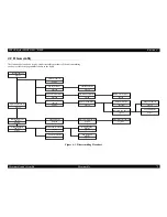
Page 72: ...moval CR motor removal ASF frame unit removal PF motor removal LD roller unit removal Board assembly removal Printer mechanism removal page 75 page 97 page 102 page 83 page 88 page 85 page 84 page 100 page 98 page 82 page 108 Housing removal page 73 Printhead removal page 79 Housing lower cover removal page 78 Paper eject roller removal page 98 CR unit removal page 102 Main board unit removal page...

Page 73: ... in the bottom of the printer the screws are situated near to the rear Figure 4 2 Removing two screws for housing 2 Remove three screws C B S 3x6 F ZN from the rear of the printer Figure 4 3 Removing three screws for housing 3 Release hooks inside the left and right panels The housing can be detached by pushing it forward to the operator Figure 4 4 Removing the left side housing C B S TITE 3x6 F Z...

Page 74: ...l C A U T I O N Tightening Torque for screw C B S TITE 3x6 F ZN screw for housing front side 6 1kgf cm C B S 3x6 F ZN screw for housing back side 6 1kgf cm Ensure that C B S TITE 3 x 6 F ZN screws are used for the two screws on the front side of the printer The tips of these screws are rounded for user s safety To detach the housing pay attention since the monochrome panel FFC is installed FFC con...

Page 75: ...he printer Refer to Section 4 2 1 Housing Removal 2 Remove 3 screws C B S 3x6 F ZN and C B P 3x8 F ZN securing the Operation Panel Assembly Then remove the Operation Panel Assembly from the Printer Mechanism Figure 4 7 Removing 3 screws for Operation Panel Tightening Torque for Screw C B S 3x6 F ZN screw for ground screw on the housing 3 5 1 kgf cm To install the housing make sure to install the F...

Page 76: ...rd 5 Remove the Panel Shield Plate and the C408PNL B board from the Operation Panel Assembly Tightening torque for screw C B S 3x6 F ZN screw for control panel cover 9 1 kgf cm C B P 3x8 F ZN screw for control panel cover 6 1 kgf cm C B P 3x8 F ZN Tightening torque for screw C B P 3x8 F ZN screw for printer panel board 6 1 kgf cm C H E C K P O I N T Removing the Operation Panel Assembly also separ...

Page 77: ... S 3x6 F ZN located on the rear of the monochrome panel board and detach the panel shield plate Figure 4 9 Monochrome panel board 4 Remove the FFC from the monochrome panel board connector C A U T I O N Pay attention since the buttons of monochrome panel will be not fixed anymore if the monochrome panel board is detached C B P 3x8 F ZN Tightening torque for screw C B S 3x6 F ZN screw for monochrom...

Page 78: ...Left Panel Housing from the printer mechanism Detach the stacker at the same time Figure 4 10 Sub Left Panel Removal 3 Remove three screws C B P 3x8 F ZN from the left housing lower cover and detach the cover Figure 4 11 Housing Lower Cover Left Removal Tightening torque for screw C B S 3x6 F ZN screw for Sub Panel Housing on the printer side 9 1 kgf cm C B P 3x8 F ZN screw for Sub Panel Housing o...

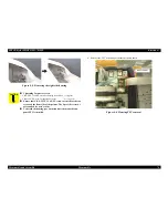
Page 79: ...e the Housing from the printer Refer to Section 4 2 1 Housing Removal 2 Open the Cover Cartridge and remove the both black and color ink cartridge 3 Remove the Cover Cartridges for black and color ink cartridges from the CR Assembly 4 Remove the Head FFC Holder from the CR Assembly by releasing two hooks Figure 4 13 Removing the Head FFC Holder 5 Disconnect the Printhead s FFC from the connector o...

Page 80: ...four portions indicated in the following Figure 4 15 Placing the Printhead s FFC Make sure that the Head Grounding Plate is installed to the carriage correctly Refer to Figure 4 16 Printhead installing the position pin the grounding plate Make sure that two holes of the Printhead correctly fit in the installing position pins Figure 4 16 Printhead installing the position pin the grounding plate Ins...

Page 81: ...rinthead 6 1 kgf cm B TITE SEMSW2 2 5x5 F ZB screw for printhead 2 0 5 kgf cm A D J U S T M E N T R E Q U I R E D When the Printhead is replaced with a new one following adjustments must be performed in the order below 1 Initial ink charge 2 Printhead ID input 3 Bi d adjustment When the Printhead is removed and reinstalled only the following adjustment is required 1 Head cleaning 2 Bi d adjustment...

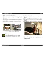
Page 82: ... Using tweezers or a small screwdriver slide the CR Lock Lever to front and release the CR Lock Lever from the CR unit 3 Loosen the CR Timing Belt by pushing the Driven Pulley Holder to right using a screwdriver and remove the Timing Belt carefully from the pinion gear on the CR motor Refer to Figure 4 17 Removing the Timing Belt Figure 4 17 Removing the Timing Belt CR Timing belt ...

Page 83: ...3x8 F ZN and detach the Sub Left Panel Housing from the printer mechanism Detach the stacker at the same time Figure 4 19 Removing the waste drain inkpad unit 3 Lift the left side of printer and disengage the hook of waste drain ink pad unit then pull out the waste drain ink pad unit to remove A D J U S T M E N T R E Q U I R E D The Gap adjustment Bi d adjustment is required when the CR motor is r...

Page 84: ...Housing Lower Cover Left Removal 4 Remove five screws as shown here Figure 4 21 Printer mechanism removal C H E C K P O I N T When attaching the waste drain inkpad check that the tip of waste ink tube is correctly placed at the specified position of waste drain inkpad If the waste ink tube is not correctly attached ink leakage may occur Refer to Figure 4 20 Tip of the waste ink tube setting positi...

Page 85: ... 2 6 Waste drain ink pad unit removal 4 Remove the printer mechanism from printer Refer to Section 4 2 7 Printer mechanism removal 5 Remove 10 screws to detach the board cover as shown below Figure 4 22 Board cover removal 6 Remove the right housing lower cover from the board assembly Refer to Section 4 2 3 2 Housing Lower Cover Right Removal C A U T I O N Be careful not to drop the waste drain in...

Page 86: ...for the ground cable Figure 4 23 Panel shield plate removal Figure 4 24 Remove the screw securing each circuit board C408 MAIN Remove nine screws C B S 3x6 F ZN Red Green circled screws 7pcs for Main board C P 3x6 F ZN Yellow circled screws 2pcs USB interface connector preview monitor connector C408 PSE Remove five screws C B S 3x6 F ZN Blue Green circled screws 5pcs for PSE board C B S 3x6 F ZN C...

Page 87: ... F ZN screw for AC120V cable 6 1kgf cm C B O 4x5 F ZG screw for Earth cable 11 1kgf cm When reassembling the main board tighten screws from lower numbers in Figure 4 22 Board cover removal When reassembling the main board and the circuit board tighten screws from lower numbers in Figure 4 24 Remove the screw securing each circuit board C H E C K P O I N T Check the Earth terminal and wire position...

Page 88: ... 26 Taking Head FFC out from the FFC holder 3 Remove two screws C B S 3x6 F ZN securing the LD roller holder to the Main frame Figure 4 27 Removing two screws securing the LD roller holder LD roller shaft holder Head FFC holder Tightening Torque for screw C B S 3x6 F ZN screw for screw securing the LD roller holder 9 1 kgf cm C B S 3x8 F ZN screw for screw securing the LD roller holder 9 1 kgf cm ...

Page 89: ... the LD roller shaft holder unit upward from the Main frame Figure 4 28 Pushing two hooks of the LD roller shaft holder 6 Remove the LD roller along with the Clutch mechanism from the LD roller shaft holder unit Figure 4 29 Removing the LD roller with Clutch mechanism Two hooks for LD roller holder Clutch mechanism LD Roller LD Roller shaft holder unit Panel shield plate ...

Page 90: ...23 2 Before assembling the LD roller shaft make sure that the round hole of the Clutch is set on the protrusion on the LD roller shaft as shown in the following figure Figure 4 31 Assembling the Clutch Assemble the LD roller shaft holder unit to the printer mechanism in the following procedure 1 Set the tip of the Change lever to the printer front side Figure 4 32 LD Roller shaft holder assembling...

Page 91: ...ocedure 2 3 Make sure the PE detection lever is the same as the following figure Figure 4 34 Correct position of the PE detection lever Paper return plate PE detection lever Fasten the LD roller shaft holder with two screws C B S 3x6 F ZN in the order indicated in the following figure Figure 4 35 Fastening the LD roller shaft holder Tightening torque for screw C B S 3x6 F ZN screw for LD roller sh...

Page 92: ...he cable from the sensor connector Figure 4 36 Removing the HP or PE detection lever 4 Release each two hooks of HP and PE sensors securing them from the LD roller then remove the sensors HP detection lever PE sensor HP sensor Fixing nooks Fixing nooks PE detection lever C H E C K P O I N T Tor Make sure that the Torsion spring 0 22 is hung to the following suitable position Figure 4 37 Torsion sp...

Page 93: ...4 2 6 Waste drain ink pad unit removal 3 Remove one screw C B S P4 3x6 F ZN and detach the pump unit cover Figure 4 40 Pump unit cover removal Tor Make sure that the HP or PE sensor cable is placed to the suitable groove on the LD roller shaft holder Figure 4 39 Sensor cable placing position Make sure that the each sensor lever turn back smoothly by moving it after the sensor was assembled to the ...

Page 94: ...k system frame 6 Release one hook for Cap assembly on the Ink system frame and take the Cap assembly out from the Ink system frame 7 Disconnect the waste drain ink tube carefully from the bottom of the Cap assembly Tightening torque for screw C B S P4 3x6 F ZN screw for pump unit cover 9 1 kgf cm C B S 3x6 F ZN screw for ink system frame and cap assembly 9 1 kgf cm C A U T I O N When the Ink syste...

Page 95: ... cleaner with oil or grease When installing the Cleaner head set the rubber side black side facing toward the right side of the frame When installing the Cleaner head set the two square cut offs on the Cleaner head into the two hooks on the Ink system Figure 4 42 Cleaner Head Assembly Cleaner head Hook cut off C A U T I O N When replacing the Cap Assembly do not touch the sealing rubber portion of...

Page 96: ...ystem frame Make sure that the ink tube is placed along the following position Figure 4 44 Ink tube placing position After installing the Pump Assembly ensure that the cleaner parts move back and forth by rotating the Gear Combination Gear 37 6 44 4 Combination Gear 9 6 24 Spur Gear 14 4 38 4 Pump Unit Cap Assembly Ink Tube Tightening torque for screw C B S 3x6 F ZN screw for ink system frame Cap ...

Page 97: ...hree nuts M3 hexagon nut securing the ASF motor to the ink system frame Figure 4 45 Removing of ASF motor 5 Disconnect the ASF motor s connector cable from the CN11 on C408 Main board 6 Remove the ASF motor from the ink system frame Hexagon Nut M3 C A U T I O N Pay attention not to damage gears when attaching the ink system unit Connect the ASF motor connector cable to the CN11 on C408 Main board ...

Page 98: ...ain washer and then remove the Combination gear 11 6 36 8 carefully Refer to Figure 4 47 Removing the combination gear 11 6 36 8 Figure 4 47 Removing the combination gear 11 6 36 8 C A U T I O N When removing the Front frame if the CR unit is out of the CR home position the nozzle surface of the Printhead may come in contact with Paper guide front as soon as the Front frame is removed This is beca...

Page 99: ...ide and remove the paper eject roller from the left side bushing Figure 4 49 Removal of Paper Eject Roller Paper Eject Roller Bush A D J U S T M E N T R E Q U I R E D When you replace the Frame front make sure to lubricate the specific amount of G26 to the Frame front Refer to the Chapter 6 Refer to Figure 6 5 Lubrication point 5 When you replace the Paper eject roller with new one make sure to lu...

Page 100: ...per Eject Roller removal 5 Remove the Plain washer and then remove the Combination gear 11 6 36 8 carefully Refer to Figure 4 51 Removing the Plain washer and Combination gear 11 6 36 8 Figure 4 51 Removing the Plain washer and Combination gear 11 6 36 8 When you assemble the Front frame to the Printer mechanism set the CR unit to the left side and assemble the Front frame from the right side Be c...

Page 101: ...eft frame Hexagon Nut M3 PF Motor C H E C K P O I N T Be sure that the PF motor cable is placed to the backward Refer to the Figure 4 53 PF motor cable Figure 4 53 PF motor cable Since the CN 12 is located near the rear edge of the Main board It is easier to use the tweezers or pincers to connect the cable to the CN12 Check that the connector cable of PF motor is securely connected to the CN12 on ...

Page 102: ...from the CR pinion gear Refer to Section 4 2 5 CR motor removal 3 Release the Printhead FFC from the cable holders on the LD roller shaft holder And disconnect the Printhead FFC from the connectors CN8 and CN9 on the Main board Figure 4 54 Taking Printhead FFC off 4 Remove the Lever PG s hook from the installation hole in the right side of the frame then remove the Lever PG Figure 4 55 Removal of ...

Page 103: ...t align it with the hole in the frame and remove it Figure 4 57 Removing bush parallel adjustment right 10 Remove the shaft CR guide together with the carriage unit from the frame 11 Remove the shaft CR guide from the carriage unit Tightening torque for screw C B S TITE P4 3x6 F ZN screw for screw securing the Bushing Parallelism adjustment right 7 1 kgf cm C B S TITE P4 3x6 F ZN Bushing Paralleli...

Page 104: ...ure 4 16 Printhead installing the position pin the grounding plate CR Slider CR Grounding Plate C H E C K P O I N T If the CR unit is disassembled or replaced with a new one make sure that the CR timing belt is set in the assembling groove correctly as following figure Figure 4 59 CR timing belt setting position A D J U S T M E N T R E Q U I R E D When you replace the CR unit with a new one lubric...

Page 105: ...using lower cover from the printer Refer to Section 4 2 3 Housing Lower Cover Removal 4 Remove the Paper Eject roller Refer to Section 4 2 13 Paper Eject Roller removal 5 Remove the CR unit Refer to Section 4 2 15 CR unit removal 6 Release the PF grounding spring from the Main frame Figure 4 60 Releasing the PF grounding spring 7 Release one hook located on the right edge of the Front paper guide ...

Page 106: ... the Front paper guide Figure 4 62 Remove the Front paper guide 9 Fit the protrusions of the Left PF roller bushing to the notches in the frames as shown in the following figure and remove the PF roller fasten spacer with tweezer Figure 4 63 Fit the protrusions of the Left PF roller bushing to each notches 10 As shown in Step 2 in the above figure slide the left roller bushing to the right side St...

Page 107: ... the hooks and the dowel pins on the Front paper guide is set to the fitting positions secure Slide the Front paper guide to the right side by pushing it and make sure that the right hook on the Front paper guide is locked to the frame securely If the Front paper guide is not fixed securely to the suitable position it may cause the paper jam problem Figure 4 65 Front paper guide assembling notice ...

Page 108: ...screws C B S TITE P4 3x8 F ZN screw C B S TITE P4 3x6 F ZN securing the ASF frame unit and remove the ASF frame unit from the printer mechanism Figure 4 66 Removing the screws securing the ASF frame 4 Remove the Spur gear 23 2 from the ASF frame Figure 4 67 Removing the Gears from ASF frame unit C B S TITE P4 3x8 F ZN C B S TITE P4 3x6 F ZN ASF Frame Unit A D J U S T M E N T R E Q U I R E D Assemb...

Page 109: ... ASF Frame and the Hopper and remove the Hopper from the ASF frame Figure 4 68 Removing the Compression spring 2 67 6 Remove the Torsion spring 25 7 from the bottom of the ASF frame and the Pad holder Paper return plate Figure 4 69 Removing the Torsion spring 25 7 ASF Hopper Compression Spring 2 67 ASF Frame ASF Frame Torsion Spring 25 7 ...

Page 110: ...e ASF Frame Pad Holder When you replace the ASF frame or Hopper with the new one make sure to lubricate the specific amount of G26 into the groove on ASF frame Refer to Figure 6 6 Lubrication point 6 and Figure 6 4 Lubrication point 4 in the Chapter 6 Fasten the ASF unit C B S TITE P4 3x8 F ZN screw left screw in the following figure C B S TITE P4 3x6 F ZN screw right screw in the following figure...

Page 111: ...emove the tilt screws and then tilt stand Figure 4 72 Tilt base removal 2 Remove two screws securing the monitor cable cover and detach the monitor cable cover Figure 4 73 Monitor cable cover removal 3 Remove the monitor cable from the hook on the rear case Figure 4 74 Monitor cable hook removal 4 Remove four screws securing the back case Figure 4 75 Removal of the back case attaching screws Tilt ...

Page 112: ...efer to 4 3 1 2 Remove one screw securing the control board unit Figure 4 77 Removal of the control board unit attaching screw 3 Remove three connectors attached to the control board unit Figure 4 78 Connectors removal 4 Remove the control board unit Connector Screw C H E C K P O I N T CN602 and CN603 are open close type connectors A D J U S T M E N T R E Q U I R E D When the control board unit is...

Page 113: ...Remove two screws securing the panel assembly and then remove the panel assembly Figure 4 79 Panel assembly removal 4 Remove the hook from shield board and detach the shield plate and panel unit Figure 4 80 Panel unit removal Panel assembly Screws Hook Shield plate Panel unit A D J U S T M E N T R E Q U I R E D When the panel unit is replaced make sure to adjust as follows Brightness adjustment Im...

Page 114: ...C H A P T E R 5 ADJUSTMENT Download Free Service Manual and Resetter Printer at http printer1 blogspot com ...

Page 115: ...lity between each printer mechanism it is necessary to set up the adjustment information for each mechanism It is therefore necessary to set up and save the correct mechanism information with the use of the adjustment program when the printer mechanisms the main circuit board and the printer head have been replaced Table 5 1 Adjustment items 1 2 3 4 5 6 7 8 Service item Parallel adjustments EEPROM...

Page 116: ... Initial position of the bush and parallel adjustor 2 Set the lever and PG to the position at the front 3 If the carriage unit is locked use a pair of pincers to press down on the lock lever and release it C A U T I O N Do not scratch of otherwise damage the specially coated surfaces of the roller and PF unit the paper guide or the surface of the front rib Clean the gap gauge with a cloth moistene...

Page 117: ...ers the gauge on the left hand side 11 Set the lever and PG at the position at the front 12 Rotate the left hand bush and parallel adjuster towards you and set them so that they are one cog tooth towards the rear in the direction where the PG is widened from the position where contact is made with the printer head If the head and gauge come into contact from the beginning rotate the bush to the re...

Page 118: ...rogram initial screen 2 Select the model name 3 Select the number of the port to which the Stylus PHOTO 895 785EPX is connected to the computer C A U T I O N This program is specially designed for use on the Windows 98 platforms It will not run on DOS Windows 3 x or NT This program runs only on USB I F Table 5 2 Individual adjustment service program No Main Menu Service 1 Adjustment EEPROM initial...

Page 119: ...Quit button to display the menu shown below Adjustments will be completed and the program ended when the Quit button is clicked The screen will return to the model selection screen when the Next button is clicked Figure 5 6 Termination C A U T I O N Do not start up the adjustment program before connecting the USB cable to the printer Be sure to restart the adjustment program if the printer power i...

Page 120: ...nts with the service program 120 5 3 3 EEPROM initial setting It is required to write the initial setting values into EEPROM when the Main board is replaced Figure 5 7 EEPROM Initial Setting Click on the OK button to write the initial setting values into EEPROM ...

Page 121: ...and then click on the OK button If Check head ID has been selected the value will be displayed in the center of the screen at the bottom If Input Head ID has been selected the following screen will be displayed to enable the head ID to be entered Figure 5 9 Input head ID Check the 13 character ID written on each of the print heads and enter the ID for the head that has been replaced Click on the O...

Page 122: ...rinter If Check present adjustment value has been selected the value will be displayed in the center of the screen at the bottom If Input Bi D adjustment value has been selected a screen to enable the adjustment value to be entered will be displayed Adjustments are required if the result of the printed Bi D adjustment pattern looks like the examples shown below The lines are not straight Figure 5 ...

Page 123: ...tion process line number 3 digits PC number 2 digits Year month date 12 digits The personal computer s time data is used for this 0 1 digit A new USB ID is created during the repair process by adding an 8 digit serial number automatically generated by the adjustment program to the end of the existing 10 digit product serial number This new USB ID is then entered into the control circuit board s EE...

Page 124: ...K button to display the current condition of memory card drive If an error message is displayed on screen replace the Main board 5 3 8 Head cleaning This function enables the heads to be cleaned forcibly from the operation panel The execution of this function will improve missing dots The following ink is to be used for head cleaning Black Unused 1 24 ink cartridge Color Unused 1 13 ink cartridge ...

Page 125: ... 3 9 Ink replenishment This function implements the initial ink replenishment process The following ink is to be used for ink replenishment Black Unused 1 8 ink cartridge Color Unused 1 4 ink cartridge Figure 5 17 Initial ink charge Click on the OK button to start the ink replenishment procedure ...

Page 126: ... and only the ink in the cap is discharged to the waste drain ink pad After complete this sequence this program set the initial ink charge flag into the EEPROM and reset the several ink consumption counters to 0 C A U T I O N After carry out this function replace the waste drain ink pad with new one and reset the Waste drain ink pad counter Otherwise the ink or S46 liquid may leak from the pad dur...

Page 127: ...n the OK button If Check the present counter value has been selected the following screen will be displayed Click on the OK button to display the counter value in the center of the screen at the bottom Figure 5 20 Check the protection counter The following screen will be displayed if Clear the protection counter value has been selected to enable the protection counter to be cleared Click on the OK...

Page 128: ...er Figure 5 22 Print A4 pattern Two pieces of A4 paper are used by the check pattern Set two pieces of A4 paper in the printer and then click on the OK button to commence printing Check the patterns printed on both pieces on paper If unacceptable areas exist make the necessary adjustments with the service program The followings show the printed samples Figure 5 23 Print sample 1 ...

Page 129: ...such as the life expectancy of the ink is stored in the EEPROM The following menu will be displayed when a tick has been added to CSIC Information on the supplementary menu Figure 5 25 CSIC information Select the item for which the information is to be displayed and then click on the OK button The required information will be displayed on screen When Print out all information is selected all infor...

Page 130: ...een added to EEPROM Data on the supplementary menu Figure 5 26 EEPROM data The EEPROM data function contains the following two functions Check the EEPROM Data This enables the EEPROM data within a range specified by an address to be confirmed Specify the address and then click on the OK button A screen that will call out the EEPROM data from the printer will be displayed Change the EEPSOM data It ...

Page 131: ... on the monochrome screen 5 When writing data starts the LED indication appears as follows Release the button Processing LED Lights up 6 Processing LED shifts as follows Lights up Æ Goes off Æ Blinks 7 When the processing LED blinks it means writing is complete Turn the power of printer OFF 8 Wait for 10 seconds after turning the power of printer OFF C H E C K P O I N T Prepare the memory card in ...

Page 132: ...e Print key then print the detail environmental setting values 2 Check the firmware version in the memory card drive Refer to the Figure 5 27 Print Example of Detail Setting Values Figure 5 27 Print Example of Detail Setting Values EPSON Stylus Photo 895 STATUS SHEET XXXXXXXX c SEIKO EPSON CORPORATION EPSON Stylus Photo 785 STATUS SHEET XXXXXXXX c SEIKO EPSON CORPORATION Firmware version Stylus PH...

Page 133: ...ure 5 28 Inspection image display procedure C A U T I O N Pay great attention not to mistake the firmware for inspection with the actual firmware since they have the same file name Table 5 3 Image pattern display order Order Image pattern Order Image pattern 1 16 level gray scales 5 Green raster 2 Color chart 6 Blue raster 3 Window 7 White raster 4 Red raster 8 Black raster Printer initial conditi...

Page 134: ...h CN600 with the rear case of preview monitor detached 3 Display the 16 level gray scales following the Figure 5 28 Inspection image display procedure 4 Turn VR501 and check that the level is variable then set it at the central click position 5 Turn the VR500 with the precision screwdriver to adjust so that the 16 levels can be the center Figure 5 29 VR instrumentation C H E C K P O I N T To check...

Page 135: ... scale Levels should be 16 levels Levels should be displayed step by step Color chart Color pattern should be 8 patterns Color order from left to right white yellow light blue green pink red blue black Window Surrounding of display section should be white Center of display section should be black Red raster Total area should be red Green raster Total area should be green Blue raster Total area sho...

Page 136: ...C H A P T E R 6 MAINTENANCE Download Free Service Manual and Resetter Printer at http printer1 blogspot com ...

Page 137: ...the surface of ASF LD Roller lowers the friction set the adhesive surface of the cleaning sheet included in the media to the surface of the ASF roller and repeat loading paper from the ASF C A U T I O N Never use chemical solvents such as thinner benzine and acetone to clean the exterior parts of printer like the housing These chemicals may deform or deteriorate the components of the printer Be ca...

Page 138: ...select code page nozzle check pattern on the status printing sheet If the ink counter value is close to its limit notify your customer and recommend that the waste ink pad be replaced If the waste ink pad is not replaced at that time there is a possibility that Maintenance Error will occur soon after the printer is returned to the customer Once you have the confirmation of the customer replace the...

Page 139: ... Type G 26 Lubrication Amount Φ1mm x 4points Use a syringe to lubricate After lubrication move the ASF hopper manually and smooth out the grease inside the ASF frame 5 Lubrication Point Specified both edges area on the Front frame Refer to Figure 6 5 Lubrication point 5 Lubrication Type G 26 Lubrication Amount Φ1mm x 200mm x 1 areas Use a syringe to lubricate After lubrication move the CR unit lef...

Page 140: ...nge to lubricate Table 6 2 Lubrication Point No Lubrication Type Point Remarks 13 Lubrication Point Cavity of the paper eject roller bush Right Refer to Figure 6 13 Lubrication point 13 Lubrication Type G 26 Lubrication Amount Φ2mm x Full circle Use a syringe to lubricate 14 Lubrication Point Roller paper stopper Refer to Figure 6 14 Lubrication point 14 Lubrication Type G 26 Lubrication Amount Φ5...

Page 141: ...N Stylus PHOTO 895 785EPX Revision A Maintenance Overview 141 Figure 6 1 Lubrication point 1 Figure 6 2 Lubrication point 2 Figure 6 3 Lubrication point 3 Figure 6 4 Lubrication point 4 G 56 G 26 G 26 G 26 ...

Page 142: ... Stylus PHOTO 895 785EPX Revision A Maintenance Overview 142 Figure 6 5 Lubrication point 5 Figure 6 6 Lubrication point 6 Figure 6 7 Lubrication point 7 Figure 6 8 Lubrication point 8 200 mm G 26 G 26 G 26 ...

Page 143: ...tylus PHOTO 895 785EPX Revision A Maintenance Overview 143 Figure 6 9 Lubrication Point 9 Figure 6 10 Lubrication point 10 Figure 6 11 Lubrication point 11 Figure 6 12 Lubrication point 12 G 26 G 26 G 26 G 26 ...

Page 144: ...ylus PHOTO 895 785EPX Revision A Maintenance Overview 144 Figure 6 13 Lubrication point 13 Figure 6 14 Lubrication point 14 Figure 6 15 Lubrication point 15 Figure 6 16 Lubrication point 16 G 26 G 26 G 26 G 26 ...

Page 145: ...C H A P T E R 7 APPENDIX Download Free Service Manual and Resetter Printer at http printer1 blogspot com ...

Page 146: ...or C408 PSE CN2 CN1 Printer Mechanism USB CN3 CN11 CN5 CN13 CN14 CN2 PE sensor PCMCIA Preview monitor Printer PNL Monochrome PNL AC power ASF motor Table 7 1 Connector Summary for C408 MAIN Connector Function Table to refer to CN1 PCMCIA Table 7 2 CN1 PCMCIA CN2 Preview monitor Table 7 3 CN2 Preview Monitor CN3 USB I F Table 1 3 Connector Pin Assignment and Signals CN4 HP sensor Table 7 4 CN4 Sens...

Page 147: ...cycle prolonged 62 BVD2 SPKR Battery voltage detection Audio digital waveform 63 BVD1 STSCHG Battery voltage detection Card status change 60 INPACK Input port response 33 WP IOIS16B Write protect I O port is 16 bits 43 VS1 Voltage sensing 1 57 VS2 Voltage sensing 2 36 CD1 Card detection 67 CD2 Card detection Table 7 3 CN2 Preview Monitor Pin Signal name I O Function 1 5V 5V power supply 2 5V 5V po...

Page 148: ...ut Serial clock 6 GND Ground 7 CH Out Waveform selection signal of the MS and variable shots 8 COC In Color I C detection signal 9 RXD Out CSIC output 10 COB In Black I C detection signal 11 TXD In CSIC output 12 VDD3 3 Logic power supply 3 3V 13 GND Ground 14 COM Head drive pulse trapezoid wave 15 GND Ground 16 COM Head drive pulse trapezoid wave 17 GND Ground Table 7 8 CN9 Printhead Pin Signal n...

Page 149: ... drive signal B 4 ASF B Out Phase drive signal B Table 7 8 CN9 Printhead Pin Signal name I O Function Table 7 11 CN12 PF Motor Pin Signal name I O Function 1 PFA Out Phase drive signal A 2 PFB Out Phase drive signal A 3 PF A Out Phase drive signal B 4 PF B Out Phase drive signal B Table 7 12 CN13 CR Motor Pin Signal name I O Function 1 CRA Out Phase drive signal A 2 CRB Out Phase drive signal A 3 ...

Page 150: ...Summary 150 12 INH Out LCD I F indication lights out 13 3 3V 3 3V power supply 14 CE Out LCD I F chip enable signal 15 5V 5V power supply 16 SCL Out LCD I F shift clock 17 DN Out LCD I F indication data Table 7 13 CN14 Monochrome PNL Pin Signal name I O Function ...

Page 151: ...rved Bit0 Reserved 00H 00H 02H 05H Ink counter Cb 00H 00H 00H 00H 06H 09H Ink counter Cy 00H 00H 00H 00H 0AH 0DH Ink counter Cm 00H 00H 00H 00H 0EH 11H Ink counter Cc 00H 00H 00H 00H 12H 15H Ink counter Clm 000H 00H 00H 00H 16H 19H Ink counter Clc 00H 00H 00H 00H 1AH Ink counter A0 00H 00H 3 1BH 00H 00H 3 1CH Ink counter Rb0 00H 00H 3 1DH 00H 00H 3 1EH Ink counter Ry0 00H 00H 3 1FH 00H 00H 3 20H C...

Page 152: ... Address Map Address Explanation Setting QPIT setting Factory setting 30H Interface selection Bit7 Reserved Bit6 Reserved Bit5 Reserved Bit4 Reserved Bit3 USB Bit2 Reserved Bit1 Parallel Bit0 Auto 00H 00H 2 31H Interface time out 0 to 255 by second value of 0 means 10seconds 0AH 0AH 32H I F Speed Bit7 Reserved Bit6 Bit5 Reserved Bit4 Bit3 ECP speed Bit2 Bit1 Compatibility speed Bit0 00H 00H 33H Bi...

Page 153: ...or Rank ID for VhU 1 n 40 00H 1 43H Head Actuator Rank ID for VhM2 1 n 34 00H 1 44H Head Actuator Rank ID for VhB 1 n 34 00H 1 45H Head Actuator Rank ID for AR 0 n 6 00H 1 46H Head Actuator Rank ID for IwB 30 n 70 00H 1 47H Head Actuator Rank ID for IwC 30 n 70 00H 1 48H Head Actuator Rank ID for IwM 30 n 70 00H 1 Table 7 14 EEPROM Address Map Address Explanation Setting QPIT setting Factory setti...

Page 154: ...P 785EPX SP Storage 0x00 0x00 0x84 0x00 0x20 0x85 0x00 0x00 0x86 0x00 0x38 or 0x37 0x87 0x00 0x00 0x88 0x00 0x39 or 0x38 0x89 0x00 0x00 0x8a 0x00 0x35 0x8b 0x00 0x00 0x8c 0x00 0x20 or 0x45 0x8d 0x00 0x00 0x8e 0x00 0x53 or 0x50 0x8f 0x00 0x00 0x90 iProduct 0x00 0x74 or 0x58 0x91 0x00 0x00 0x92 0x00 0x6f or 0x20 0x93 0x00 0x00 0x94 0x00 0x72 or 0x53 0x95 0x00 0x00 0x96 0x00 0x61 or 0x74 0x97 0x00 0x...

Page 155: ... 1 0xb3 0x00 0x00 0xb4 0x00 1 Table 7 15 EEPROM Address Map Address Field Description QPIT Setting Factory Setting 0xb5 iSerial 0x00 0x00 0xb6 0x00 1 0xb7 0x00 0x00 0xb8 0x00 1 0xb9 0x00 0x00 0xba 0x00 1 0xbb 0x00 0x00 0xbc 0x00 1 0xbd 0x00 0x00 0xbe 0x00 1 0xbf 0x00 0x00 0xc0 0x00 1 0xc1 0x00 0x00 0xc2 0x00 1 0xc3 0x00 0x00 0xc4 0x00 1 0xc5 0x00 0x00 0xc6 0x00 1 0xc7 0x00 0x00 0xc8 0x00 0x00 0xc9...

Page 156: ... 15 EEPROM Address Map Address Field Description QPIT Setting Factory Setting 0xd4 Panel Settings Initial setting for Index print mode 1 Upper 4bits Default of Paper Type 0x00 Premium Glossy Photo Paper 0x10 Photo Quality Ink Jet Paper 0x20 Plain Paper 0x30 Photo Paper 0x40 Matte Paper Heavyweight Lower 4bits Default of Paper Size 0x00 89mm Roll 0x01 127mm Roll 0x02 4 Roll 0x03 210mmRoll 0x04 4x6 ...

Page 157: ...Lower 4bits Default of Quality 0x00 High 0x01 Normal 0x00 0x00 0xdc Initial setting for Set print mode Upper 4bits Default of PhotoEnhance 0x00 On 0x10 Off Lower 4bits Reserved Don t care 0x00 0x00 0xdd Reserved 0x00 0x00 0xde 0x00 0x00 Table 7 15 EEPROM Address Map Address Field Description QPIT Setting Factory Setting 0xdf Reserved 0x00 0x00 0xe0 Detailed environment Trimming 0x00 Enabled 0x01 D...

Page 158: ...e specific value to the product Available characters are 0 to 9 and A to Z 0xf0 Reserved 0x00 0x00 0xf1 0x00 0x00 0xf2 0x00 0x00 0xf3 0x00 0x00 0xf4 0x00 0x00 0xf5 0x00 0x00 0xf6 0x00 0x00 0xf7 0x00 0x00 0xf8 0x00 0x00 0xf9 0x00 0x00 0xfa 0x00 0x00 0xfb 0x00 0x00 0xfc 0x00 0x00 0xfd 0x00 0x00 0xfe 0x00 0x00 0xff 0x00 0x00 Table 7 15 EEPROM Address Map Address Field Description QPIT Setting Factory...

Page 159: ...EPSON Stylus PHOTO 895 785EPX Revision A Appendix Exploded Diagram 159 7 2 Exploded Diagram ...

Page 160: ... 132 107 400 400 106 105 125 125 125 104 122 125 743 732 731 730 127 123 744 138 125 137 125 111 125 122 450 451 136 122 103 737 124 180 For JPN 331 117 118 Without JPN EAI LATIN ECC EKL ETT 181 182 183 184 185 750 749 748 747 747 No 01 Rev 01 10304 PM 790PT EPSON STYLUS PHOTO 785EPX 895 122 For JPN ...

Page 161: ...2 122 712 122 122 330 300 200 122 122 122 122 122 122 709 718 708 802 803 806 803 801 800 121 122 705 704 122 131 145 114 114 122 114 736 710 144 706 No 02 Rev 01 10304 PM 790PT EPSON STYLUS PHOTO 785EPX 895 714 500 711 336 Without JPN ETT 122 ...

Page 162: ...531 738 700 532 565 536 537 535 568 550 565 566 543 543 543 545 567 552 595 564 546 587 512 545 547 587 546 530 560 546 546 545 546 511 549 549 547 546 595 741 545 545 545 544 544 544 544 544 545 511 No 03 Rev 01 10304 PM 790PT EPSON STYLUS PHOTO 785EPX 895 06 546 547 545 ...

Page 163: ...8 587 575 585 522 716 539 571 539 540 539 539 540 574 580 576 715 556 556 587 503 505 126 572 507 542 541 542 542 541 599 601 573 577 600 502 587 590 506 734 541 551 581 582 583 596 570 520 519 510 523 589 588 504 509 735 591 501 595 586 584 746 No 04 Rev 01 10304 PM 790PT EPSON STYLUS PHOTO 785EPX 895 587 556 126 552 ...

Page 164: ...Tilt Screw Screw 2x12 Back Case Screw 2x6 Front Case Cover Sheet Panel Unit Shield Plate Screw 2x6 Control Board Unit Monitor Cable Cover Monitor Cable Screw 2x12 Tilt Bolt Tilt Stand ...

Page 165: ...C B P TITE SCREW 3X8 F ZN 126 C B S SCREW 131 GASKET PC CARD 132 BUTTON PRINT START 133 BUTTON STOP 134 BUTTON FRAME 135 BUTTON CROSS KEY 136 SHIELD PLATE PANEL LCD B 137 HOUSING PANEL SUPPORT RIGHT 138 HOUSING PANEL SUPPORT LEFT 139 COVER COLOR LCD 140 COVER LCD C 141 TAPE 21X62 142 TAPE 4X36 143 TAPE 3 5X50 144 HOUSING SUPPORT LEFT 145 HOUSING SUPPORT RIGHT 146 STACKER SUPPORT MIDDLE B 147 STACK...

Page 166: ...LER PF 523 BUSH ROLLER PF B 524 BUSH ROLLER PF LEFT B 525 SPACER FASTEN ROLLER PF Table 7 16 Parts List Code Name 526 GROUNDINGWIRE PF 527 C RING 528 PLANE WASHER 12 2X0 5X15 530 CARRIAGE C 531 SHAFT CR GUIDE 532 SLIDER CR 533 GROUNDING PLATE HEAD 534 SCALLOP SPRING PIN AW 2X16 F B 535 ROLLER ASSY EJ 536 PAPER GUIDE FRONT B 537 POROUS PAD PAPER GUIDE FRONT B 539 TORSION SPRING 87 9 540 PAPERGUIDE ...

Page 167: ... 578 HARNESS DETECTOR PE 580 COMPRESSION SPRING 4 80 581 SPUR GEAR 35 2 582 CLUTCH 583 EXTENSION SPRING 0 143 Table 7 16 Parts List Code Name 584 SHAFT ROLLER LD SUPPORT 585 SHAFT ROLLER LD B 586 ROLLER LD 587 C B S SCREW 588 COMBINATION GEAR 14 4 38 4 589 COMPRESSION SPRING 2 94 B 590 MOTOR ASSY ASF 591 TRAY IS 592 HOLDER CABLE HEAD B 593 CABLE HEAD 594 SHEET PROTECTION SMALL 595 C B S TITE P4 3X...

Page 168: ...E B 734 CLEANER HEAD ASP 735 POROUS PAD INK EJECT CAP LOWER D 736 HEXAGON NUT 737 PAPER GUIDE LOWER 738 COVER CARTRIDGE BK B 739 COVER CARTRIDGE C B 740 PLATE SPRING COVER CARTRIDGE 741 BIND B TITE SEMS W2 2 5X5 F ZB 743 POROUS PAD INK EJECT UPPER B 744 STOPPER PAPER GUIDE LOWER 746 SUPPORT PLATE HOLDER SHAFT B Table 7 16 Parts List Code Name 747 IDLE ROLLER 748 HOLDER IDLE ROLLER 749 SPRING HOLDE...

Page 169: ...uits 169 7 4 Electrical Circuits The electric circuit diagrams below are shown at the following pages C408 MAIN control circuit board 1 2 C408 MAIN control circuit board 2 2 C408PSB C408PSE C408 PNL circuit board C408PNL B circuit board Preview monitor circuit board ...

Page 170: ......

Page 171: ......

Page 172: ......

Page 173: ......

Page 174: ......

Page 175: ......

Page 176: ......

Reviews: