EPSON Stylus COLOR 900/900N
Chapter 4 Disassembly and Assembly
99
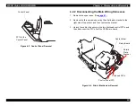
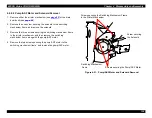
9. Remove the two actuators for the ink cartridge sensors. (Note that
the black one is for the black cartridge and the white one is for the
color cartridge.)
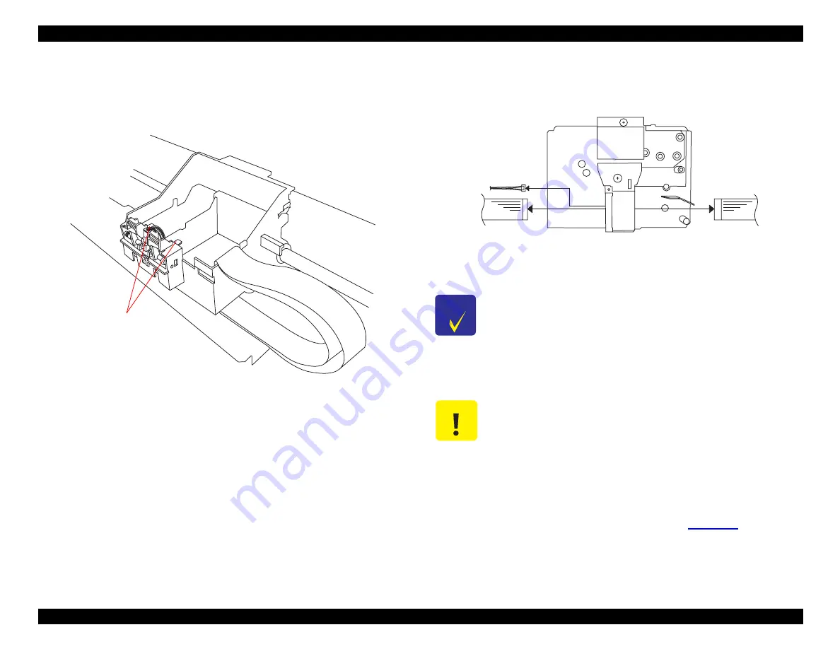
Figure 4-16. Printer Mechanism Removal (2)
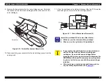
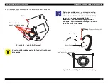
10. Disconnect the green connector for the ink cartridge sensor from the
carriage unit.
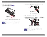
11. Lift up the printhead unit, and then disconnect the two FFCs and the
connector (green, 4-pin) for the ink cartridge sensors.
Figure 4-17. Printer Mechanism Removal (3)
A ctua to rs
C H E C K
P O I N T
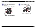
Install the printhead FFCs as described below:
White one: on the left side of the printhead.
Blue one: on the right side of the printhead.
C A U T I O N
If you replace the printhead, turn on the printer and
wait for the Ink Out error before installing new
cartridges. If you install new cartridges before
turning on the printer, an internal conflict between the
EEPROM and the head ID value may cause the printer
to give an Ink Out error even with the new cartridges
installed.
After removing or replacing the printhead, perform
any necessary adjustments. (See
Green
White
Blue
Summary of Contents for 900N
Page 1: ...EPSONStylusCOLOR900 900N Color ink jet printer TM SC900 N 6 59 0 18 ...
Page 8: ... 37 5 PRODUCTDESCRIPTION ...
Page 37: ... 37 5 OPERATINGPRINCIPLES ...
Page 67: ... 37 5 TROUBLESHOOTING ...
Page 89: ... 37 5 DISASSEMBLYANDASSEMBLY ...
Page 121: ... 37 5 ADJUSTMENTS ...
Page 156: ... 37 5 MAINTENANCE ...
Page 169: ... 37 5 APPENDIX ...
Page 179: ...EPSON Stylus COLOR 900 900N Chapter 7 Appendix 176 Figure 7 3 C265 Main Board Soldering side ...
Page 181: ...EPSON Stylus COLOR 900 900N Chapter 7 Appendix 178 Figure 7 6 C265 PNL Board ...
Page 195: ...06 03 01 02 for S E ASIA 03 03 05 03 04 EPSON STYLUS COLOR 900 No 7 10056 Rev 01 ...
Page 197: ......
Page 198: ......
Page 199: ......
Page 200: ......
Page 201: ......

