EPSON Stylus COLOR 900/900N
Chapter 5 Adjustments
122
Check the contents of your CONFIG.SYS file, and add the following
command line if it’s not already present:
Device=c:\<path name>\ansi.sys or
Devicehigh=c:\<path name>\ansi.sys
The device driver
ansi.sys enables escape sequence characters to
display properly on the screen. Replace <path name> with the
name of the directory containing your ansi.sys file. (If you’re not sure
where the ansi.sys file is located, you can use the Find tool in
Windows Explorer to locate it.)
Check the contents of your autoexec.bat file, and add the following
command line if it’s not already present:
Mode lpt1:retry=p
This command resends failed transmissions of raster data, and
defines the number of retries to the printer port as
permanent.
The adjustment program is designed to run in the Windows
environment (for example, if you launch it from Windows Explorer).
However, this does not work on all systems. If the program stalls or
you experience communication problems between your computer
and the printer, try the following:
Make sure the ECP printer port setting is turned off.
If this doesn’t work, restart your computer in DOS emulation
mode and launch the adjustment program from the DOS prompt.
If you’re still having trouble, turn off your printer and keep it off
for at least 10 seconds. Then turn it back on, let it initialize, and
launch the adjustment program from the DOS prompt.
5.2.2 Starting the Adjustment Program
To start the adjustment program and get to its main menu, follow these
steps:
1. Connect the printer to your computer’s LPT1 port using a parallel
cable.
2. Turn the printer on.
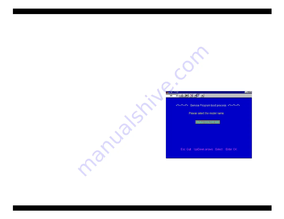
3. Launch the adjustment program (SC900.EXE) either from Windows
Explorer or by restarting the computer in DOS emulation mode and
typing the program’s name at the DOS prompt. Either way, the
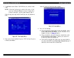
following screen appears:
Figure 5-1. Welcome Screen
Summary of Contents for 900N
Page 1: ...EPSONStylusCOLOR900 900N Color ink jet printer TM SC900 N 6 59 0 18 ...
Page 8: ... 37 5 PRODUCTDESCRIPTION ...
Page 37: ... 37 5 OPERATINGPRINCIPLES ...
Page 67: ... 37 5 TROUBLESHOOTING ...
Page 89: ... 37 5 DISASSEMBLYANDASSEMBLY ...
Page 121: ... 37 5 ADJUSTMENTS ...
Page 156: ... 37 5 MAINTENANCE ...
Page 169: ... 37 5 APPENDIX ...
Page 179: ...EPSON Stylus COLOR 900 900N Chapter 7 Appendix 176 Figure 7 3 C265 Main Board Soldering side ...
Page 181: ...EPSON Stylus COLOR 900 900N Chapter 7 Appendix 178 Figure 7 6 C265 PNL Board ...
Page 195: ...06 03 01 02 for S E ASIA 03 03 05 03 04 EPSON STYLUS COLOR 900 No 7 10056 Rev 01 ...
Page 197: ......
Page 198: ......
Page 199: ......
Page 200: ......
Page 201: ......

