EPSON Stylus COLOR 900/900N
Chapter 5 Adjustments
152
15. Remove the thickness gauge and place it on the far-left end of the
platen (80th-column position). Then adjust the left parallelism
adjustment bushing in the same way as you did the right one.
5.3.2 Checking the Platen Gap
After adjusting the platen gap, follow these steps to make sure it’s set
correctly:
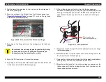
1. Place the thickness gauge on the right end of the platen.
2. Move the blue PG lever to the rear to raise the carriage.
3. By pulling on the timing belt, move the carriage over the thickness
gauge.
4. Move the PG lever forward to narrow the platen gap.
5. By pulling on the timing belt, slide the carriage back and forth over
the thickness gauge and make sure the thickness gauge does not
move.
6. Rotate the right parallelism adjustment bushing upward one notch
and then make sure that the thickness gauge moves.
7. Return the right parallelism adjustment bushing to the previous
position by turning it downward one notch.
8. If the printhead fails to come in contact with the thickness gauge in
step 6, repeat the PG adjustment for the left bushing.
9. When the adjustment is successful, tighten the screws on both
bushings. While turning the screws, hold the bushings in place with
your hand so they don’t move.
10. Remove the thickness gauge.
11. Remove the partially used or empty ink cartridges.
12. Move the carriage to home position.
13. Install the upper case.
C A U T I O N
When you’re checking the adjustment, make sure the
PG lever is set forward (narrower gap).
When you’re repositioning the carriage, move the
PG lever to the rear to increase the platen gap and
prevent damage to the printhead.
C H E C K
P O I N T
Check to make sure the linear scale (timing strip) is not
dislocated from the sensor slot on the back of the
carriage.
Summary of Contents for 900N
Page 1: ...EPSONStylusCOLOR900 900N Color ink jet printer TM SC900 N 6 59 0 18 ...
Page 8: ... 37 5 PRODUCTDESCRIPTION ...
Page 37: ... 37 5 OPERATINGPRINCIPLES ...
Page 67: ... 37 5 TROUBLESHOOTING ...
Page 89: ... 37 5 DISASSEMBLYANDASSEMBLY ...
Page 121: ... 37 5 ADJUSTMENTS ...
Page 156: ... 37 5 MAINTENANCE ...
Page 169: ... 37 5 APPENDIX ...
Page 179: ...EPSON Stylus COLOR 900 900N Chapter 7 Appendix 176 Figure 7 3 C265 Main Board Soldering side ...
Page 181: ...EPSON Stylus COLOR 900 900N Chapter 7 Appendix 178 Figure 7 6 C265 PNL Board ...
Page 195: ...06 03 01 02 for S E ASIA 03 03 05 03 04 EPSON STYLUS COLOR 900 No 7 10056 Rev 01 ...
Page 197: ......
Page 198: ......
Page 199: ......
Page 200: ......
Page 201: ......


