EPSON Stylus COLOR 900/900N
Chapter 2 Operating Principles
48
2.3.4.1 Power-Off Timer/Reset Circuit
The RTC9810 produces a reset signal by monitoring both the 5 VDC
line (input to pin 7) and 42 VDC line (input to pin 9). When the voltage
level for the 5 VDC line is below 4.3 V, or the voltage level for the
42 VDC line is below 35.5 V, the circuit outputs a reset signal from
pin 2. This occurs, for example, when the printer is first turned on, and
serves to reset the logic chips to prevent abnormal operation of the
driver systems.
The reset chip also includes an internal timer circuit (oscillator) to keep
track of how long the printer has been off. This lets the printer determine
whether to perform a cleaning cycle at the next power-on, and, if so,
which type of cleaning to perform.
While the printer is on, it supplies 5 V at pin 7 to operate the internal
timer circuit; however, when the printer is off, a 3-volt lithium cell battery
powers the timer circuit through pin 8.
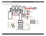
Figure 2-14.
Power-Off Timer/Reset Circuit
+ 4 2 V
S p e e d u p
d i o d e
+ 5 V
R 1 8 1 0 7 K
R 2 0 1 0 K
B A T 1
V I N
V D D
V B K
G N D
9
7
8
1 4
/R
S
T
CE
SC
LK
DA
TA
4 3
8 1
H D 6 4 F 2 3 5 7 ( I C 1 )
E 0 5 B 5 9 ( I C 2 )
2
4
5
6
/R
S
T
3 6
E 0 5 B 6 0 ( I C 3 )
2 5
2 6
2 7
TC
E
TC
LK
TD
A
TA
R T C 9 8 1 0 ( I C 8 )
/R
S
T
/R
S
T
L B 1 8 4 7 ( I C 1 1 )
2
1 3
V R E F 1
V R E F 2
3 . 0 V
2
1 3
M 6 2 3 8 3 ( I C 1 7 )
1 2
/ R S T
D / A x x
D / A y x
D / A x y
3
4
8
L B 1 8 4 7 ( I C 1 2 )
V R E F 1
V R E F 2
A 3 9 5 7 ( I C 1 3 )
R E F
A 3 9 5 7 ( I C 1 4 )
R E F
3
3
D e v i s i o n
D r o p s t o 3 5 V
Voltage Divider
Drops to 3.5 V
Summary of Contents for 900N
Page 1: ...EPSONStylusCOLOR900 900N Color ink jet printer TM SC900 N 6 59 0 18 ...
Page 8: ... 37 5 PRODUCTDESCRIPTION ...
Page 37: ... 37 5 OPERATINGPRINCIPLES ...
Page 67: ... 37 5 TROUBLESHOOTING ...
Page 89: ... 37 5 DISASSEMBLYANDASSEMBLY ...
Page 121: ... 37 5 ADJUSTMENTS ...
Page 156: ... 37 5 MAINTENANCE ...
Page 169: ... 37 5 APPENDIX ...
Page 179: ...EPSON Stylus COLOR 900 900N Chapter 7 Appendix 176 Figure 7 3 C265 Main Board Soldering side ...
Page 181: ...EPSON Stylus COLOR 900 900N Chapter 7 Appendix 178 Figure 7 6 C265 PNL Board ...
Page 195: ...06 03 01 02 for S E ASIA 03 03 05 03 04 EPSON STYLUS COLOR 900 No 7 10056 Rev 01 ...
Page 197: ......
Page 198: ......
Page 199: ......
Page 200: ......
Page 201: ......


