EPSON Stylus COLOR 900/900N
Chapter 3 Troubleshooting
81
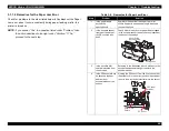
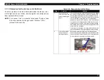
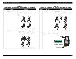
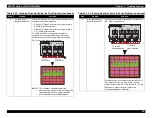
Table 3-26. ASF Solenoid Does Not Operate
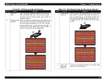
Table 3-27. ASF Solenoid Does Not Operate (continued)
Step
Problem
Solution
1
Is fuse F4
open?
Place the meter’s probes on both terminals of the chip
fuse on the C265 Main board, then check for electrical
continuity. Fuse F4 is located between CN12 and CN16
and also beside Q9.
2
Is transistor Q8
defective?
Place the probe of the oscilloscope on the collector side
of transistor Q8 on the C265 Main board, and then check
that the voltage holds steady at 40 VDC. (Q8 is located
between CN12 and CN16.) Then press the Load/Eject
button and check if the voltage drops briefly to 0 VDC. If
it does, it means that Q8 is working properly.
Q 8
2 0 V 2 0
2 0 V 2 0
µ
µ
Step
Problem
Solution
3
Is transistor Q9
defective?
Place the probe of the oscilloscope on the emitter side of
transistor Q9 on the C265 Main board, and then check
that no voltage is present. (Q9 is located beside CN16.)
Then press the Load/Eject button and check that the
voltage jumps to 40 VDC. If it does, then Q9 is working
properly.
4
Is the C265
Main board
defective?
If you haven’t isolated the problem in the previous steps,
replace the C265 Main board.
Q 9
2 0 V 2 0
2 0 V 2 0
+
µ
µ
Summary of Contents for 900N
Page 1: ...EPSONStylusCOLOR900 900N Color ink jet printer TM SC900 N 6 59 0 18 ...
Page 8: ... 37 5 PRODUCTDESCRIPTION ...
Page 37: ... 37 5 OPERATINGPRINCIPLES ...
Page 67: ... 37 5 TROUBLESHOOTING ...
Page 89: ... 37 5 DISASSEMBLYANDASSEMBLY ...
Page 121: ... 37 5 ADJUSTMENTS ...
Page 156: ... 37 5 MAINTENANCE ...
Page 169: ... 37 5 APPENDIX ...
Page 179: ...EPSON Stylus COLOR 900 900N Chapter 7 Appendix 176 Figure 7 3 C265 Main Board Soldering side ...
Page 181: ...EPSON Stylus COLOR 900 900N Chapter 7 Appendix 178 Figure 7 6 C265 PNL Board ...
Page 195: ...06 03 01 02 for S E ASIA 03 03 05 03 04 EPSON STYLUS COLOR 900 No 7 10056 Rev 01 ...
Page 197: ......
Page 198: ......
Page 199: ......
Page 200: ......
Page 201: ......


