EPSON Stylus COLOR 900/900N
Chapter 4 Disassembly and Assembly
90
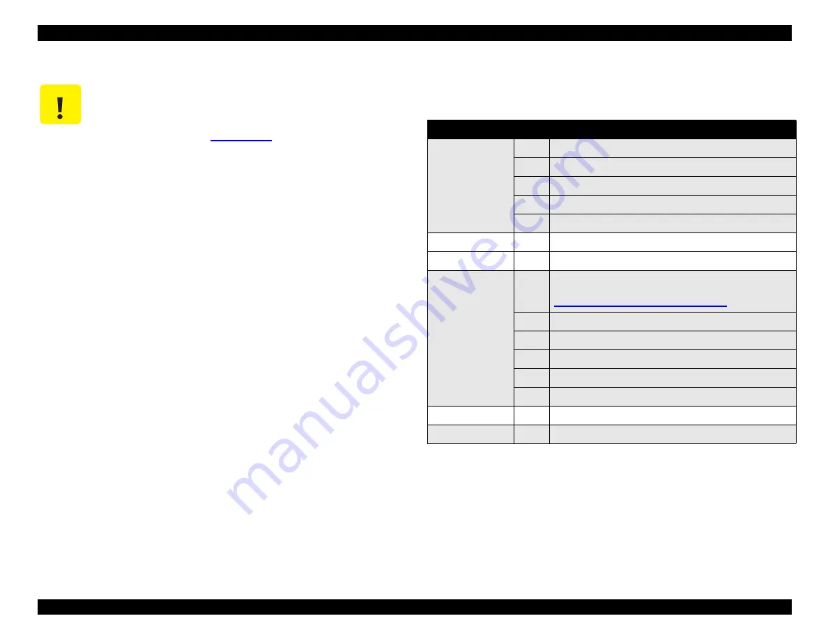
Table 4-1.
Adjustments You Must Make After Repairing the Printer
* You don’t need to perform these steps if you reinstalled the old parts without
replacing them with new ones.
C A U T I O N
When you remove or replace certain parts, you must
make the required adjustments. Perform all
adjustments indicated in the table below, following the
order as shown. See
details.
Part Replaced
Order
Adjustments Required
Printhead
1
Enter the I/C replacement sequence and install a new I/C.
2*
Head Actuator Voltage ID Input
3*
Ink Charge Flag Reset
4
Head Angular Adjustment
5
Bi-Directional Adjustment
C265 Main board
1*
Head Actuator Voltage ID Input
2*
Bi-Directional Adjustment
CR shaft
1
Clean and lubricate the carriage guide shaft, and replace
the oil pad on the back of the carriage. (See
"Lubricating the Carriage Guide Shaft"
2
Platen Gap Adjustment
3
Enter the I/C replacement sequence and install a new I/C.
4
Ink Charge Flag Reset
5
Head Angular Adjustment
6
Bi-Directional Adjustment
Waste Ink Pad
1*
Clear the protection counter value.
CR Motor
1*
Bi-Directional Adjustment
Summary of Contents for 900N
Page 1: ...EPSONStylusCOLOR900 900N Color ink jet printer TM SC900 N 6 59 0 18 ...
Page 8: ... 37 5 PRODUCTDESCRIPTION ...
Page 37: ... 37 5 OPERATINGPRINCIPLES ...
Page 67: ... 37 5 TROUBLESHOOTING ...
Page 89: ... 37 5 DISASSEMBLYANDASSEMBLY ...
Page 121: ... 37 5 ADJUSTMENTS ...
Page 156: ... 37 5 MAINTENANCE ...
Page 169: ... 37 5 APPENDIX ...
Page 179: ...EPSON Stylus COLOR 900 900N Chapter 7 Appendix 176 Figure 7 3 C265 Main Board Soldering side ...
Page 181: ...EPSON Stylus COLOR 900 900N Chapter 7 Appendix 178 Figure 7 6 C265 PNL Board ...
Page 195: ...06 03 01 02 for S E ASIA 03 03 05 03 04 EPSON STYLUS COLOR 900 No 7 10056 Rev 01 ...
Page 197: ......
Page 198: ......
Page 199: ......
Page 200: ......
Page 201: ......


