background image

Chapter 1

Setting Up Your System

This chapter briefly describes how to set up your computer. It
includes the following information:

 Unpacking your computer

Setting the voltage selector switch

 Connecting system components

Turning the computer on and off

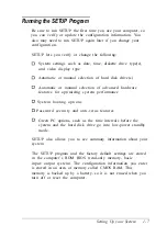
 Running the SETUP program

 Post-SETUP procedures.

Unpacking Your Computer

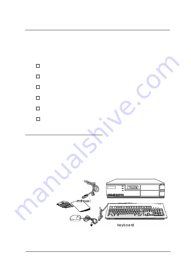
When you unpack your system, make sure you have the items

shown below.

p o w e r
cord

computer

diskettes

mouse

Setting Up Your System

1-1

Summary of Contents for ActionPC 3000

Page 1: ...E P S O N User s Guide EPA POLLUTION PREVENTER 89 Printed on recycled paper with 10 post consumer content ...

Page 2: ...anical photocopying recording or otherwise without the prior written permission of Epson America Inc No patent liability is assumed with respect to the use of information contained herein Nor is any liability assumed for damages resulting from the use of the information contained herein Further this publication and features described herein are subject to change without notice TRADEMARKS EPSON is ...

Page 3: ...into the extension cord does not exceed the cord s ampere rating Also make sure the total of all devices plugged into the wall outlet does not exceed 15 amperes Except as specifically explained in this User s Guide do not attempt to service the computer yourself Adjust only those controls that are covered by the operating instructions Unplug the computer and refer servicing to qualified service pe...

Page 4: ... cordon d alimentation de l ordinateur n est pas abime ni effiloche l Dans le cas ou on utilise un cordon de rallonge avec l ordinateur s assurer que l intensite en amperes requise pour tous les appareils branches sur ce cordon ne soit pas superieure a la capacite du cordon S assurer aussi que cette intenste ne depasse jamais la somme de 15 amperes pour l ensemble des appareils l Sauf dans les cas...

Page 5: ...4MB 0 System and video BIOS shadow RAM 0 8KB of internal cache integrated into the microprocessor and support for up to 256KB of optional external cache memory on the main system board 0 Integrated high speed local bus SVGA video interface 0 512KB expandable to 1MB or 1MB of on board video memory 0 Video resolutions up to 1280 x 1024 in 16 colors with 1MB of VRAM 0 True Color support in the 640 x ...

Page 6: ...ve to install option cards You can use the option slots to enhance your system with extra functions such as a modem card a network controller card or additional interface ports The shadow RAM feature allows your system to speed up processing by moving the system and video BIOS into the RAM area of memory Video The local bus SVGA video interface provides data transfer at the full speed of the proce...

Page 7: ...ndby mode because it isn t receiving video signals from your computer Screens on non compliant monitors go blank but do not enter a low power standby mode VGA Drivers Your computer comes with VGA drivers and utilities for use with the integrated video interface With these drivers you can take advantage of the extended VGA features such as higher resolutions and 132 column text mode when you run po...

Page 8: ...system to 1MB which allows you to use higher resolutions with more colors Your system supports a variety of microprocessors including 5 Volt 3 3 Volt 3 45 Volt and 3 6 Volt processors see Chapter 3 for more information You can increase the external cache memory size to 64KB 128KB or 256KB by installing cache SRAM chips on the main system board allowing you to access data faster and improve overall...

Page 9: ...dures resetting the computer using the Green PC features and changing the processor speed Chapter 3 describes how to remove and replace the computer s cover change jumper settings and install optional equipment such as option cards and memory modules Chapter 4 explains how to install and remove drives Chapter 5 contains troubleshooting tips Appendix A lists the specifications of your computer At t...

Page 10: ... Care Center Customer Relations EPSON technical information library fax service Product literature on current and new products You can purchase accessories manuals or parts for EPSON products from EPSON Accessories at 800 873 7766 U S sales only In Canada call 800 GO EPSON for sales locations When you call for technical assistance be ready to identify your system and its configuration and provide ...

Page 11: ...f CompuServe you are eligible for a free introductory membership as an owner of an EPSON product This membership entitles you to 0 An introductory 15 credit on CompuServe 0 Your own user ID and password 0 A complimentary subscription to CompuServeMagazine CompuServe s monthly publication To take advantage of this offer call 800 848 8199 in the United States and Canada and ask for representative 52...

Page 12: ...h 1 2 Connecting System Components 1 4 Connecting the Power Cord 1 5 Turning Your System On and Off 1 5 Running the SETUP Program 1 7 Starting the SETUP Program 1 8 The System Setup Option 1 9 The Fixed Disk Setup Option 1 10 The Advanced System Setup Option 1 11 Setting the Boot Options 1 13 The System Security and Anti Virus Options 1 15 Using the Green PC Features 1 18 The System Summary Option...

Page 13: ... length Slot Installing a Card in a Half length Slot Removing an Option Card Adding Video Memory Installing External Cache Installing the External Cache Chips Upgrading the Microprocessor Replacing the Processor Chip Post installation Procedures 3 2 3 4 3 5 3 6 3 8 3 9 3 11 3 12 3 14 3 15 3 16 3 17 3 18 3 20 3 21 3 23 3 24 3 26 Chapter 4 Installing and Removing Drives Removing the Drive Mounting B...

Page 14: ...rt The Computer Does Not Respond Keyboard Problems Mouse Problems Monitor Problems Diskette Problems Diskette Drive Problems Hard Disk Drive Problems Password Problems Software Problems Printer Problems Option Card Problems Memory Module Problems Controller Problems External Cache Problems Appendix A Specifications 5 1 5 3 5 4 5 5 5 5 5 6 5 7 5 8 5 8 5 10 5 11 5 12 5 12 5 13 5 14 5 14 CPU and Memo...

Page 15: ...e Option Information Options Available from EPSON Tested Operating Environments D M A A s s i g n m e n t s H a r d w a r e I n t e r r u p t s S y s t e m M e m o r y M a p System I O Address Map Connector Pin Assignments Glossary A 6 A 7 A 8 A 10 A 11 A 12 A 12 A 13 A 14 A 14 A 16 Index v i i i ...

Page 16: ...Unpacking your computer 0 Setting the voltage selector switch 0 Connecting system components 0 Turning the computer on and off 0 Running the SETUP program 0 Post SETUP procedures Unpacking Your Computer When you unpack your system make sure you have the items shown below power cord computer diskettes mouse Setting Up Your System 1 1 ...

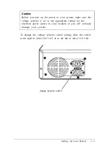
Page 17: ...this switch to 110 VAC or 220 VAC EPSON ships the computer with the voltage selector switch set to 110 VAC This setting is appropriate for line source voltages between 100 and 120 VAC and is generally the appropriate setting to select if you plan to use your computer in North America South America or Japan If you plan to operate the computer in the United Kingdom Europe or some South American coun...

Page 18: ...o the appropriate setting for the electrical power source in your location or you will seriously damage your system To change the voltage selector switch setting slide the switch to the right to select 220 VAC or to the left to select 110 VAC voltage selector switch Setting Up your System 1 3 ...

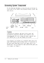
Page 19: ...eyboard are physically identical they cannot be used interchangeably Be sure to plug the mouse connector into the MOUSE port or you may damage your system Your computer also includes two removable panels above the mouse and keyboard ports providing access to a game port on the main system board and to one on an option card if you installed one You can enable the main system board game port via a j...

Page 20: ...r cord into an appropriate grounded electrical outlet After you connect the components of your system you are ready to turn on the power Turning Your System On and Off Before you turn on your system be sure to read the Important Safety Instructions at the beginning of this manual Caution If there is a protective card in a diskette drive remove it now or you may damage your drive First turn on the ...

Page 21: ...er indicator lights up After a few seconds the computer performs its power on diagnostics This is a series of everything is working correctly If necessary use the controls on your monitor to adjust the on the screen Whenever you turn off your system be sure to save your data the hard disk drive light and the diskette drive light s to make sure they are not on Press the power button to turn off the...

Page 22: ...dware features for optimizing system performance 0 System booting options 0 Password security and anti virus features 0 Green PC options such as the time intervals before the system and the hard disk drive go into low power standby mode SETUP also allows you to see summary information about your system The SETUP program and the factory default settings are stored in the computer s ROM BIOS read on...

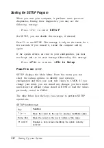
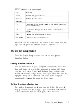
Page 23: ... F 1 t o r e s u m e F 2 t o S e t u p Press F2 to run SETUP SETUP displays the Main Menu From this menu you can select the various options to identify your system s configuration and then save your new values to CMOS If you change your mind you can cancel any changes you have made and restore the default values stored in ROM or load the values previously stored in CMOS The table below lists the k...

Page 24: ...tup Option From the System Setup screen you can set the options described below Setting the time and date The real time clock in your computer continuously tracks the date and time even when the computer is turned off Once you set the System Time and System Date options you should not need to change them unless you adjust the time for daylight savings or a different time zone The computer automati...

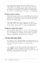
Page 25: ... s are securely seated in their sockets See Chapter 3 to locate the SIMM sockets Setting the diskette drive type s On your system diskette drive A is the 3 5 inch high density drive installed in your computer You may also have another drive of a different size or capacity this is drive B Check the settings for both drives and correct them if necessary The Fixed Disk Setup Option The options on the...

Page 26: ...an define your own type To define your own drive type follow these steps 1 Move the cursor to Type and select User 2 Type the values in each field that are appropriate for your hard disk drive 3 When you exit SETUP make sure you save your changes The Advanced System Setup Option When you select this option from the Main Menu you see the Advanced System Setup screen which contains the options descr...

Page 27: ...emory shadow The system can configure the Memory Shadow options or you can manually set them You can enable or disable shadowing of your system and video memory and control the specific blocks of ROM used for this purpose Your computer can access RAM faster than ROM The options on this screen allow your system to copy the contents of its system and or video ROM into RAM When you use shadowing your...

Page 28: ...ng for the parallel port is AT mode for unidirectional operation Setting the Boot Options When you select Boot Options from the Main Menu you see the Boot Options screen which contains the options described below Selecting the drive boot sequence The Disk drive boot sequence option determines the order in which the computer checks the drives when it looks for the operating system If you select A t...

Page 29: ...ressing F2 within the allowed amount of time Disabling power on diagnostic error messages The Pause on POST errors option allows you to disable the error message and the message Press F1 to r e s u m e F2 to Setup that you see when the system identifies a configuration error If you disable this option the system ignores configuration errors it finds during power on diagnostics and starts as it nor...

Page 30: ...t option you must enter the Supervisor or User password each time you turn on the system If you do not enable this option but you have defined passwords you must enter the password each time you start the SETUP program If both a Supervisor and User password are enabled SETUP displays options for setting the User password only for users who logged on with a user password To specify a User password ...

Page 31: ... must delete the User password before SETUP will allow you to access the Supervisor password If you have forgotten your password s see Password Problems in Chapter 5 Using the virus protection features Several options on the Security and Anti Virus screen allow you to define system protection features The Diskette Access option allows you to restrict access to your diskette drives based on the pas...

Page 32: ...rotect your system by selecting Write p r o t e c t f o r t h e F i x e d d i s k b o o t s e c t o r o p t i o n When this option is enabled the system displays an error message when a program tries to write to the boot sector of your hard disk drive To use a legitimate program such as the MS DOS FORMAT command you must disable the write protect option Two additional options on this screen allow ...

Page 33: ... computer Screens on monitors that aren t Energy Star compliant will go blank when your system is in standby mode If you select a time period for the Lockout Timer as well as the Inactivity Timer 1 option the system won t accept your keyboard input for the specified period of time after your system has returned to an active mode This allows time for your monitor to return to full power also The Fi...

Page 34: ...lso return all values to the factory defaults To leave SETUP press ESC from any SETUP screen From the Main Menu you can do the following Load ROM Default Values Loads the factory default settings s t o r e d i n R O M b a c k i n t o CMOS I f y o u c h a n g e y o u r s y s t e m c o n f i g u r a t i o n a n d t h e n h a v e p r o b l e m s y o u c a n l o a d t h e R O M v a l u e s t o b o o t...

Page 35: ...on programs If your computer was configured for you these drivers are already installed The README files on Drivers Diskettes 1 and 2 provide instructions for installing and using the drivers To read the file on your screen insert Drivers Diskette 1 in drive A type the following and press Enter A README To print the file to your printer type the following and press Enter A READMEP Use the same com...

Page 36: ...ably This section provides some tips for creating a comfortable work environment 0 Use good posture Keep your elbows hips and knees bent at approximately 90 degree angles and keep your wrists as close to horizontal as possible 0 Vary your posture often and take frequent breaks Stand up stretch and move around 0 Use a good chair Make sure your chair supports your lower back A chair with padded armr...

Page 37: ... directly in front of you and sit about an arm s length away from it The top of the screen should be slightly below your eye level so you look down at the screen Position the monitor so that no light is reflected from the screen Stopping a Command or Program You may sometimes need to stop a command or program while it is running If you have entered an MS DOS or application program command that you...

Page 38: ...iting a program you may lose data Also do not remove a diskette or reset or turn off the computer while a diskette drive light is on You could lose data Be sure to remove all diskettes before you turn off the computer To reset the computer press Ctrl Alt Del The screen displays nothing for a moment and then the computer reloads your operating system You can also press the RESET button located in t...

Page 39: ...ave paper and storage space too 0 Use recycled paper whenever you can Using Your Green PC Features Your computer places the system the hard disk drive or both into a low power standby mode when the keyboard or mouse has been inactive for the time periods you select in SETUP See Chapter 1 for information on setting these values When your system is in standby mode the Num Lock light on your keyboard...

Page 40: ...When your computer is operating at fast speed the SPEED light on the front panel is on When the computer is operating at slow speed the light is off You should use fast speed for almost everything you do because your programs will work faster However certain application programs have specific timing requirements and can run only at the slower speed See your application software manual to determine...

Page 41: ... can use the commands listed above while you are running a program However if the program uses one of these commands for another function you cannot use it to change the processor speed 2 6 Using Your Computer ...

Page 42: ...when you are finished It then describes the following 0 Locating the internal components 0 Changing the jumper settings 0 Installing and removing memory modules 0 Installing and removing option cards 0 Adding video memory 0 Adding cache memory 0 Upgrading the microprocessor Caution Never install options or change jumper settings with the computer turned on or the power cord connected to the comput...

Page 43: ...y external devices 2 Disconnect the computer s power cable from the electrical outlet and from the back panel Also disconnect any cables that are connected to the computer including the keyboard cable 3 If the monitor is on top of the computer lift it off and set it to one side 4 Turn the computer around so the back panel is facing you 5 Remove the three screws securing the cover to the back panel...

Page 44: ... to the computer by touching the metal surface of the back panel WARNING Be sure to ground yourself by touching the back panel of the computer every time you remove the cover If you are not properly grounded you could generate an electric shock that could damage a component when you touch it Installing and Removing Options 3 3 ...

Page 45: ...es are out of the way so they do not catch on the cover 4 Insert the lip at the front of the cover between the front bezel and the computer case and guide it straight down See the illustration on page 3 3 5 Replace the three cover retaining screws 6 Reconnect the computer to the monitor printer keyboard and any other peripheral devices you have Then reconnect the power cable to the back of the com...

Page 46: ... the major components on your system board external rc rkn sot kl microprocessor J15 J2 J2L J2E J2E hard dis drive connec J33 k tor J31 J17 option ca connect board rd I or J30 _ video J14 J13 Jll memory r I I keyboard Pod J4 SlMM sockets I diskette drive iD J5 JE J6 J7 connector J8 JA JB JC Installing and Removing Options 3 5 ...

Page 47: ...HDC IDE hard disk drive controller J4 1 2 Enablesgame port J1 2 3 Disables game port J1 J5 1 2 Assigns the parallel port as LPT1 378h 37Fh 2 3 Assigns the parallel port as LPT2 278h 27Fh J6 1 2 Assigns serial port 1 as COM1 3F8h 3FFh 2 3 Assigns serial port 1 as COM3 3E8h 3EFh J7 1 2 Assigns serial port 2 as COM2 2F8h 2FFh 2 3 Assigns serial port 2 as COM4 2E8h 2EFh J8 1 2 Enablesthe diskette driv...

Page 48: ...or Microprocessor type jumpersettings Default setting dependson the type of factory installed microprocessor Microprocessor voltage jumper settings 1 1 To determine the voltage of your microprocessor see page 3 23 2 Default setting 3 The setting of J33 does not matter if you are using a 5 VoIt microprocessor Built in VGA controller jumper settings Function J14 J15 Enable built in VGA controller ID...

Page 49: ...he Jumpers If you need to change any jumper settings follow these steps 1 Refer to the illustration on page 3 5 to locate the jumpers 2 If the jumper you need to change is blocked by any option cards installed in your computer you need to remove the card s to access the jumpers See page 3 17 3 To move a jumper from one position to the other use needle nose pliers or tweezers to pull it off its pin...

Page 50: ...ts on the main system board and each can contain one SIMM You can use 1MB 2MB 4MB 8MB 16MB and 32MB SIMMs The following table shows the possible SIMM configurations do not install memory in any other configuration The labels on the system board identify the sockets Bank 0 and Bank 1 where you should install SIMMs SIMM configurations Bank 0 1MB 1MB 2MB 2MB 1MB 4MB 4MB 4MB 4MB 8MB 8MB Bank 1 Total m...

Page 51: ... properly 0 Use only tin plated 72 pin 32 bit or 36 bit fast page mode SIMMs that operate at an access speed of 80ns nanoseconds or faster Be sure all the SIMMs operate at the same speed 0 Use the correct SIMM configuration to add the amount of memory you want See the table above 3 10 Installing and Removing Options ...

Page 52: ...o install SIMMs 1 Refer to the illustration on page 3 5 to locate the SIMM sockets 2 Remove any option cards that may be blocking your access to the SIMM sockets See page 3 17 for instructions 3 Position the first SIMM at an angle over the first empty socket in the bank you are filling as shown below The components on the SIMM should face the computer s power supply Installing and Removing Options...

Page 53: ...force it pull it all the way out and try again 5 Repeat steps 3 and 4 for the other SIMM if necessary 6 Replace any option cards you removed See page 3 14 for instructions Removing SIMMs If you need to remove SIMMs from your computer to install different ones for example follow the steps below 1 Remove any option cards that may be blocking your access to the SIMM sockets See page 3 17 for instruct...

Page 54: ...he SIMM at each end as shown below As you pull away the tabs the SIMM falls to the side Remove it from the socket 3 If necessary follow the same procedure to remove the other SIMM 4 Replace any option cards you removed as described in the next section Installing and Removing Options 3 1 3 ...

Page 55: ...k the option card do not touch any of the components on the circuit board or the gold edged connectors Place it gently on top of its original packing material with the component side facing up Keep the packing materials in case you remove the card later 0 Before you install the card adjust any switches or jumpers on it if necessary See the instructions that came with the card Also see if you need ...

Page 56: ... safe place in case you remove the option card later 3 Hold the card along the top corners and guide it into the slot as shown below If you are installing a full length card insert the front edge of the card into the corresponding guide inside the computer s front panel Once the connectors reach the slot push the card in firmly but carefully to insert it fully You should feel it fit into place If ...

Page 57: ... Follow these instructions to install a card in one of the half length slots 1 Remove the retaining screw securing the slot cover bracket Remove the bracket by lifting it straight up and out of the small meta1 holder at the bottom t dot coverbracket 2 Remove the slot cover 3 16 Installing and Removing Options ...

Page 58: ... your computer to access components on the main system board to change a jumper setting for example You may also want to remove a card if you no longer need it Refer to the illustrations on pages 3 15 and 3 16 as you follow these steps 1 If you are removing a card from one of the full length slots first remove the retaining screw securing the option card to the computer Then pull the card straight...

Page 59: ...s or for supporting video resolutions up to 1280 x 1024 in 16 colors See Appendix A for information on supported colors and resolutions for each amount of video memory The table below lists the video DRAM DIP chips that are approved for use in your computer Video DRAM DIP chip types Manufacturer Part number Goldstar GM71C256A 70 80 I 1Fiji MB81C256A 70 80 I NMBS AAA1M204P 70 50 Toshiba TC514256AP ...

Page 60: ...l them Remove the memory chips from their package and inspect each one The pins should point inward at slightly less than a 90 angle If any of the pins are not in this position use your fingers or small tweezers to gently align them with the other pins Be careful the pins are fragile and can break off easily Position one of the memory chips over the socket as shown below aligning the pins on the c...

Page 61: ...n install 64KB 128KB or 256KB of external cache on your system 0 To install 64KB of external cache use eight SRAM 28 pin 8K x 8 20ns DIP chips and one 8K x 8 20ns tag chip 0 To install 128KB of external cache use four SRAM 28 pin 32K x 8 20ns DIP chips and one 8K x 8 20ns tag chip 0 To install 256KB of external cache use eight SRAM 28 pin 32K x 8 20ns DIP chips and one 32K x 8 20ns tag chip The ta...

Page 62: ...ow to install cache memory chips contact the EPSON Connection and ask for assistance Installing the External Cache Chips Follow these steps to install the external cache chips 1 Locate the external cache memory sockets on the main system board shown on page 3 5 2 If there is an option card in your way remove it See page 3 17 for instructions Caution To avoid generating static electricity and damag...

Page 63: ...ll tweezers to align them with the other pins Be careful when you do this the pins are fragile and can break off easily Position one of the cache chips over the first socket as shown below aligning the pins on the chip with the holes in the socket Make sure the small notch on the end of the chip is aligned with the corresponding notch on the socket U26 U25 U24 U23 Gently press the chip halfway int...

Page 64: ...ssor Intel or Cyrix 5 Volt 486DX 40 processor Cyrix 5 Volt 486DX 50 processor Intel or Cyrix 5 Volt 486DX2 50 processor Intel or Cyrix 5 Volt 486DX2 66 processor Intel or Cyrix Intel 5 Volt Cyrix 5 Volt or 3 6 Volt SX2 50 processor Intel 5 Volt DX4 75 processor Intel or Cyrix Intel 3 45 Volt Cyrix 5 Volt DX4 100 processor Intel or Cyrix Intel 3 3 Volt Cyrix 5 Volt Pentium OverDrive Intel 5 Volt pr...

Page 65: ...processor chip Then remain as stationary as possible while you install it Do not touch the pins on the processor chip handle it only by the edges of its case 2 If there are any option cards in your way remove them See page 3 17 for instructions 3 Open the ZIF socket by lifting up the ZIF handle The handle rests under a plastic tab Press the handle down and away from the tab then rotate the handle ...

Page 66: ...aution If you install the processor chip in the wrong orientation you may damage the chip and void your warranty 7 Make sure the pins in the processor chip are directly over the holes in the socket Then gently push the microprocessor straight into the socket pressing evenly on all sides If you are installing a 486 chip rather than a Pentium OverDrive processor you ll see an extra row of holes arou...

Page 67: ...d of processor you installed See the table on page 3 23 for more information Follow the instructions included with the heat sink if you need to install one If the heat sink comes with a fan install it using the instructions that came with the heat sink and fan kit 11 If you removed any option cards replace them now see page 3 15 to replace a full length card or page 3 16 to replace a half length c...

Page 68: ...bays you can install a second diskette drive or another type of drive To install or remove a drive first remove the computer s cover as described in Chapter 3 Then remove any option cards that may be in your way Once you have installed the drive replace any option cards you removed See Chapter 3 for instructions Follow the appropriate instructions in this chapter to install and remove drives 0 Rem...

Page 69: ...bracket You may also have a hard disk drive installed in the bracket In order to install or remove any drives in the computer you must first remove the drive mounting bracket Follow these steps 1 Remove the two cables from the diskette drive as shown below Grasp the connectors and pull them straight out so you do not bend the pins do not pull on the cables If necessary remove the cables from the h...

Page 70: ...he Mounting Bracket You can install a hard disk drive below the diskette drive in the mounting bracket after you have removed the bracket and drive from the computer In order to fit in this space your hard disk drive must be 1 inch high by 3 inches wide If you have a larger hard disk drive you can install it in one of the drive bays see page 4 15 Installing and Removing Drives 4 3 ...

Page 71: ...t be configured as the master which contains the operating system and the other as the slave A table of jumper settings for high capacity EPSON drives is included in Appendix A Also you may need to know the number of cylinders heads sectors etc if the hard disk drive auto sensing feature in SETUP is unable to correctly identify your drive The hard disk drive table used in the SETUP program is incl...

Page 72: ...here may be a plastic guiderail and metal grounding plate attached to one of the mounting frames If so remove the screws securing them to the mounting frame and remove the guiderail and grounding plate plastic guiderail metal mounting frames 2 Then remove the two screws securing each mounting frame to the drive and remove the frames Installing and Removing Drives 4 5 ...

Page 73: ...ed on the board You will need to know the location of pin 1 when you connect the hard drive cable pin 1 Installing the Hard Disk Drive Follow these steps to install the hard disk drive in the mounting bracket 1 With the drive components facing down slide the drive into the bracket until the front of the drive is nearly flush with the edge of the bracket 4 6 Installing and Removing Drives ...

Page 74: ...2 Align the holes in the drive with the oval shaped holes in the bracket 3 Secure the drive with two or four screws depending on the location of the holes Installing and Removing Drives 4 7 ...

Page 75: ...s into the mounting area and slide it forward guiding the front of the diskette drive through the drive slot in the front panel of the computer 2 Make sure the holes in the bracket are aligned with the holes in the drive bay and brace Then secure the bracket with the screws you removed previously 4 8 Installing and Removing Drives ...

Page 76: ...necting the cables to the diskette drive Connecting the drive cable to the system board Follow the steps below to connect the hard drive ribbon cable to the system board if it is not already connected 1 Locate the hard disk drive ribbon cable it is a flat cable with three connectors that came in the box with your computer All the connectors on this cable look the same system board connector for se...

Page 77: ... pin 1 of the connector on the system board There is a 1 printed on the system board to identify pin 1 pin 1 4 Make sure the holes in the connector fit over the pins then push in the cable connector Caution If you do not correctly align the holes with the pins you could severely damage your system board when you push in the cable connector 4 10 Installing and Removing Drives ...

Page 78: ... on the drive connector If you do not see it on the connector casing and you did not locate it before you replaced the drive bracket you may have to remove the drive and turn it over to check the circuit board See page 4 14 for instructions on removing the drive and page 4 6 for instructions on locating pin 1 on the drive connector 3 Position the connector on the cable so that the red wire aligns ...

Page 79: ...the power supply They have multi colored wires and a plastic connector on the end 6 Position the power supply cable connector so that its notched corners line up with the notched corners of the power supply connector on the hard disk drive 7 Make sure the holes fit over all the pins and then push in the connector 4 12 Installing and Removing Drives ...

Page 80: ...so that the red wire is next to pin 1 Push in the connector Caution If you do not align the cable connector correctly you could severely damage your drive when you push it in 3 Locate the power supply cable with the small connector 4 Position the power supply connector so that the holes fit over all the pins and the red wire on the cable aligns with pin 1 on the drive s power connector Push in the...

Page 81: ...onnectors and pull them straight out so you do not bend the pins do not pull on the cables Remove the screws securing the bracket to the drive bay and brace Slide the bracket away from the front of the computer and lift it out P Remove the screws securing the hard disk drive to the bracket and slide the drive out of the bracket Replace the bracket using the instructions on page 4 8 4 14 Installing...

Page 82: ...alling a second hard disk drive you need to check the settings of the drive s jumpers to be sure they are correct for your configuration A table of jumper settings for high capacity EPSON drives is included in Appendix A If your drive is not listed or you need more information see the documentation that came with your drive or contact the manufacturer Before you can install a drive in one of the e...

Page 83: ... grounding plate Then go to Installing the Drive on page 4 17 Follow these steps to attach mounting frames to a drive 1 Locate the two mounting frames and four screws that came with the drive 2 As shown below place a mounting frame on one side of the drive and align it so that the oval holes in the frame are positioned over the holes in the drive Then secure the mounting frame to the drive with th...

Page 84: ...pper or lower external drive bay 1 Remove the faceplate from the drive bay by pushing it out from the inside of the computer Keep the faceplate in a safe place in case you remove a drive later or you are installing a hard disk drive Installing and Removing Drives 4 17 ...

Page 85: ...it is flush with the front of the computer 3 Align the slots at the side of the drive bay with the mounting holes in the drive or mounting frames Then secure both sides of the drive to the bay using the retaining screws 4 18 Installing and Removing Drives ...

Page 86: ...nal bay you need to purchase a new hard disk drive cable that can reach both drives If you are installing another type of drive see the documentation that came with it to connect the drive cable then go to step 3 below to connect the power supply cable 1 Locate the diskette drive ribbon cable the connector in the middle is already connected to the system board 2 If you are installing a drive with ...

Page 87: ...wires and a plastic connector on the end 4 Align the notched corners of the power supply cable connector with the notched corners of the drive s power connector such as the one shown below Make sure the holes lit over all the pins and then push in the connector notched corners Caution If you do not align the connectors correctly you could severely damage your drive when you push them in 4 20 Insta...

Page 88: ...t replace the drive mounting bracket and reconnect the cables See page 4 8 for instructions Removing a Drive from an External Bay To remove a drive from an external bay follow these steps 1 Remove the drive mounting bracket See page 4 2 for instructions 2 Disconnect both the ribbon cable connector and the power cable connector from the drive you are removing from the external bay 3 Remove the scre...

Page 89: ...gently pressing on the other side until it snaps into place 6 Replace the drive mounting bracket and reconnect the cables See page 4 8 for instructions Post installation Procedures After you install or remove your drive s and replace the cover on your computer you need to run the SETUP program to define your new configuration See Chapter 1 for instructions 4 22 Installing and Removing Drives ...

Page 90: ...ry a more specific problem is described with possible solutions If the suggestions here do not solve the problem contact your Authorized EPSON Servicer or the EPSON Connection See Where to Get Help in the Introduction of this manual for instructions Identifying Your System When you request technical assistance be ready to provide the serial number of your computer its system BIOS version number it...

Page 91: ...rsions CONFIG SYS AUTOEXEC BAT VER and press Enter to see the MS DOS version number In Windows applications select About from the Help menu As your software application starts it usually displays a version number on the banner screen Also you can check your software manual At the MS DOS prompt type T Y P E C C O N F I G S Y S and press Enter to see a listing of your CONFIG SYS file which contains ...

Page 92: ...it Make sure the power cord is securely connected to both the AC inlet on the back panel and an electrical outlet The power cord is securely connected but the computer still does not start Check the electrical outlet for power Turn off your computer and unplug the power cord Plug a lamp into the outlet and turn it on You installed or removed system components and now your computer does not start C...

Page 93: ... of time press Ctrl Alt Del If that doesn t work press the RESET button You may have installed SIMMs with an incorrect access speed Install the correct SIMMs See Chapter 3 Your system may have over heated Make sure you have an adequate heat sink installed on your microprocessor if necessary See Chapter 3 for more information You reset the computer but it still does not respond Try turning the comp...

Page 94: ...ant monitors the time they need to return to an active mode Wait a few seconds and try again See The Computer Does Not Respond above The cursor keys on the numeric keypad do not work properly If the Num Lock light in the upper right corner of the keyboard is lit press NumLock to turn off the function Mouse Problems Yourmouse isn t working properly or you see an auxiliary device error message Make ...

Page 95: ...y connected to the computer If you installed a display adapter card make sure your monitor type matches the card type Also be sure you set the correct display type in SETUP see Chapter 1 and that the main system board jumpers are set correctly see Chapter 3 If you are running an application program see if you need to set up the program for the type of monitor and display adapter you have Also make...

Page 96: ...ting the diskette does not solve the problem insert the diskette in another diskette drive of the same type If you can read the diskette in a different drive your drive may be faulty The diskette is the tight type but you still see an error Check that the diskette is not write protected preventing the drive from writing to the diskette Make sure the diskette is formatted See your operating system ...

Page 97: ...mputer Run the SETUP program and configure your system for the correct type of diskette drive The diskette drive is making loud or unusual noises Contact your Authorized EPSON Servicer or the EPSON Connection Hard Disk Drive Problems A newly installed hard disk drive is not working properly or its performance is not what you expect Make sure you have installed the drive correctly and check all cab...

Page 98: ...re data on the hard disk drive If the hard disk drive has been in low power standby mode make sure the drive has had time to achieve its full operating speed before you try to write data to it If your drive was not configured make sure you have partitioned and formatted it correctly for your operating system See your operating system manual for instructions Also make sure your hard disk drive has ...

Page 99: ...ON Servicer or the EPSON Connection Password Problems You have forgotten your password You must discharge your CMOS memory To do this you need to change the setting of jumper J30 to position 3 4 See Chapter 3 for details on changing the jumper setting After you have changed J30 restart your system leave it on for a few seconds then turn it off again This resets the SETUP values to their factory de...

Page 100: ...e reading from or writing to the hard disk drive If you have enabled the Fixed Disk Timeout option in SETUP your application may be timing out during the few second delay when the hard disk drive returns to its operating speed after being in standby mode Disable this option in SETUP see Chapter 1 Yourapplication haslocked the computer making it unresponsive to keyboard commands Reset the computer ...

Page 101: ... the printer manual for the printer s correct DIP switch or control panel settings Also make sure you have the proper drivers installed for your printer and make sure you ve selected the correct printer within your software application Option Card Problems A newly installed option card is not working correctly Make sure the option card is installed correctly and is well seated in its slot Run SETU...

Page 102: ...d in the lowest 16 bit option slot An external device connected to the option card is not working correctly Make sure you are using the proper cable to securely connect the device to the card Memory Module Problems The memory count displayed by the power on diagnostics program is incorrect You may have installed the SIMMs incorrectly They may be the wrong type or speed or they may not be inserted ...

Page 103: ...tics program is incorrect You may have installed the external cache chips incorrectly They may be the wrong type or they may not be inserted all the way Also make sure the tag chip you ve installed has a 20ns access speed Also you may not have changed the SETUP program or the jumpers to recognize the new cache Make sure you have set the External cache option to Enabled and set both the System shad...

Page 104: ... video signals the computer sends to the monitor time periods selectable in SETUP Fast and slow processor speeds available fast speed is the speed of your processor and slow speed is 8 MHz speed selection through keyboard commands ISA bus speed for all processors is 8 33 MHz local bus video operates at the speed of your processor at fast speed DX2 50 and DX2 66 processors run internally at 50 and ...

Page 105: ...M expandable to 1MB using four 20 pin 70ns 256KB DIP chips Supports shadowing of system and video BIOS ROM into RAM Supports relocation of 256KB of memory from A0000h to BFFFFh and D0000h to EFFFFh to extended memory 8KB of internal cache supports 64KB 128KB or 256KB of external cache using 28 pin 8K x 8 or 32K x 8 20ns DIP chips Math coprocessor built into the microprocessor for DX DX2 and system...

Page 106: ... in controller BIOS provides hard disk auto sensing function lnterfaces Monitor Parallel VGA interface for fixed or multi frequency monitor built into system board low power standby mode for Energy Star compliant monitors 15 pin D shell connector One standard S bit parallel bidirectional interface built into main system board 25 pin D shell connector operation controllable by SETUP option Serial T...

Page 107: ...board accessible by removing game port slot cover on back panel operation selectable by jumper Speaker Internal Mass Storage Internal mounts for One 3 inch wide one inch high internal drive Externally accessible mounts for One 3 inch wide one inch high drive and two 5 inch wide half height drives Diskette drives 3 5 inch diskette drive 720KB or 1 44MB storage capacity 5 25 inch diskette drive 360K...

Page 108: ...chable two button PS 2 compatible SETUP Program Stored in ROM accessible by pressing F2 during boot System security User and Supervisor level passwords available for system boot or diskette access Virus protection Write protection feature for the hard disk drive boot sector periodic reminder message for running virus detection utility Physical Characteristics width 16 8 inches 430 mm Depth 15 6 in...

Page 109: ...ard five to mass storage devices Maximum current 5 Volts 5 Volts 12 Volts 12 Volts For all slots 12 Amps 0 4 Amp 4 Amps 0 4 Amp Based on a system containing one hard disk drive and one diskette drive Environmental Requirements Condition Temperature Humidity non condensing Altitude Operating range 41 to 95 F 5 to 35 C 8 to 80 330 to 9 900 ft 100 to 3 000 m Non operating range 4 to 140 F 20 to 60 C ...

Page 110: ...Video Resolutions and Colors Specifications A 7 ...

Page 111: ...eature When you press Enter with the cursor positioned on the Autotype Fixed Disk option in SETUP the system detects the type of hard disk drive you have installed and fills in the drive information using values in the following table Hard disk drive types A 8 Specifications ...

Page 112: ...Hard disk drive types continued Actual formatted size may be slightly different than size on drive label you cannot change thisvalue Specifications A 9 ...

Page 113: ...lnformation Hard disk drive options for high capacity 1 inch IDE drives Select 1 or none for the precomp value If neither of these optionsare available select the maximum available precomp value A 10 Specifications ...

Page 114: ...rounded and a slave if pin 28 is not grounded Options Available from EPSON Many options for supplementing this product are available from EPSON including the following Monitors Keyboards Mass storage devices Printers Operating system software Call your nearest marketing location for more information about specific options Specifications A 11 ...

Page 115: ...crosoft Windows 3 0 and later Microsoft Windows WorkGroups Microsoft Windows NT Your system has also received Novell s Yes NetWare tested and approved certification as a workstation and a server As new environments become available these also will be tested DMA Assignments Level 1Assigned device DMA0 Reserved 8 bit DMA1 Reserved 8 bit DMA2 I Diskette drive controIler 8 bit I DMA3 Reserved 8 bit DM...

Page 116: ...from IRQ controller 2 IRQ3 Serial port 2 IRQ4 Serial port 1 IRQ5 Parallel port 2 IRQ6 FDD controller IRQ7 Parallel port 1 IRQ8 Real time clock IRQ9 Reserved IRQ10 Reserved IRQ11 Reserved IRQ12 PS 2 mouse IRQ13 Math coprocessor IRQ14 HDD controller IRQ15 Reserved Specifications A 13 ...

Page 117: ... address 000 01F 020 03F 022 024 034 038 03C 040 05F 060 06F 070 07F 080 09F 0A0 0BF 0C0 0DF OF0 OF1 0F8 OFF 1F 1F8 200 207 278 27F 280 2DF Assigned device DMA controller 1 8237 Interrupt controller 1 8259 Chip set configuration registers AD12 chip set configuration registers Timer 8254 Keyboard controller 8042 NMI non maskable interrupt DMA page register 74LS612 Interrupt controller 2 8259A DMA c...

Page 118: ...System I O address map continued Specifications A 15 ...

Page 119: ...Error lnit Selectin Signal ground Pin 19 20 21 22 23 24 25 Signal Signal ground Signal ground Signal ground Signal ground Signal ground Signal ground Signal ground Active low logic Serial port connectorpin assignments CN7 and CN6 Pin Signal Pin Signal 1 Data carrierdetect 6 Data set ready 2 Receive data 7 Request to send 3 Transit data 8 Clear to send 4 Data terminal ready 9 Ring indicator 5 Groun...

Page 120: ... access it faster Your computer includes 8KB of internal cache in the microprocessor and has support for up to 256KB of external cache on the main system board CONFIG SYS file A special system file that MS DOS executes each time you turn on or reset the computer You use this file to customize your system by installing device drivers setting limits for files and buffers and specifying MS DOS comman...

Page 121: ...ndard Architecture The 8 or 16 bit bus standard developed for IBM compatible computers Jumper A small moveable plug that connects two pins on a device s circuit board A jumper determines the operation of a particular function Local bus An internal group of wires that sends information from the microprocessor directly to the video controller in the computer Local bus video provides increased perfor...

Page 122: ...emory that runs programs and temporarily stores data while you work See also ROM Real time clock A battery powered clock in the computer that keeps track of the current time and date even when the computer s power is off Read Only Memory The portion of the computer s memory that contains permanent instructions and cannot be modified Unlike RAM ROM retains its contents even after you turn off the c...

Page 123: ...lel Shadow RAM The function that copies the system BIOS and video BIOS from ROM into RAM to speed up performance SIMM See Memory Module VGA Video Graphics Array A high resolution 640 x 480 display adapter standard Write protect To prevent a diskette from being overwritten When a diskette is write protected you cannot erase change or record over its contents 4 Glossary ...

Page 124: ...3 A 14 video Intro 1 2 A 2 Boot options 1 13 14 5 3 Booting system 1 8 1 10 Brightness 1 6 5 6 Buttons power 1 6 RESET 1 6 2 3 C Cache memory banks 3 21 configuration 1 12 3 21 configuring 1 12 external Intro 1 Intro 4 3 20 23 5 14 A 2 installing 3 20 23 internal Intro 1 A 2 jumpers 3 8 3 22 problems with 5 14 setting in SETUP 1 12 3 23 sockets 3 21 Card LAN Intro 2 modem Intro 2 option see Option...

Page 125: ...ling access 1 14 5 7 A 5 errors 5 8 faulty 5 7 installing 4 1 3 4 8 9 4 13 4 15 21 jumper 3 6 latch 5 7 Diskette drive continued lights 1 6 post installation 4 22 power cable 4 19 21 5 8 problems 5 8 removing 4 1 3 4 21 22 support Intro 2 types A 4 Diskette s access controlling 1 14 5 7 A 5 defective 5 7 formatted 5 7 key 2 5 5 11 problems 5 7 type 5 7 write protected 5 7 Display adapters 1 9 5 6 ...

Page 126: ...uiderail 4 5 installing Intro 4 4 1 12 4 15 21 jumpers 3 6 4 4 5 8 A 11 light 1 6 mounting frames 4 4 5 Hard disk drive continued option information A 10 11 parameters A 8 10 physical format 5 9 post installation 4 22 preformatted 1 11 problems 5 8 10 removing 4 1 3 4 14 4 21 22 SETUP option 1 10 11 standby mode Intro 3 1 18 2 4 5 5 9 5 11 A 1 support Intro 2 time out 1 18 translation mode A 10 ty...

Page 127: ...o Lockout timer option 1 18 5 5 Low level format 5 9 Mass storage Intro 2 Intro 4 4 1 A 4 5 Math coprocessor Intro 2 A 2 Memory cache see Cache memory clearing 2 3 CMOS RAM 1 7 8 1 19 3 7 A 2 extended 1 10 A 14 installing see SIMMs insufficient 5 11 map A 14 problems 5 13 RAM Intro 4 5 11 A 2 relocation A 2 A 14 removing see SIMMs ROM 1 7 1 12 1 19 A 2 A 14 shadow see Shadow RAM SIMMs see SIMMs si...

Page 128: ...quipment Intro 4 1 2 3 1 4 1 A 11 Outlet electrical 1 4 5 5 3 OverDrive Pentium 3 25 A 1 2 A 4 P Parallel port connector 1 4 controller A 3 jumper settings 3 6 operation 1 11 1 13 5 12 pin assignments A 16 type Intro 1 A 3 Password on boot option 1 16 problems 5 10 Supervisor 1 15 16 5 7 A 5 User 1 15 16 5 7 A 5 Pause key 2 2 Pause on POST errors 1 14 Pentium OverDrive 3 25 A 1 2 A 4 Physical char...

Page 129: ...ons see Video resolutions Serial number 5 2 Serial ports COM1 and COM2 1 4 controller A 3 jumper settings 3 6 pin assignments A 16 reassigning 3 6 type Intro 1 SETUP program advanced chipset control 1 13 advanced system setup 1 11 12 auto configuration 1 13 autotype fixed disk 1 10 A 8 boot options 1 13 14 5 3 cache memory 1 12 chipset registers 1 13 date and time 1 9 display prompt 1 8 1 14 displ...

Page 130: ...s 3 6 7 local bus Intro 1 A 3 utilities Intro 4 System BIOS Intro 1 2 1 7 1 10 5 2 A 2 3 A 14 System Security and Anti Virus options 1 15 17 A 5 System Setup option 1 9 10 System Summary option 1 14 1 19 T Tag SRAM 3 21 Tape drive Intro 4 4 1 4 15 A 3 A 5 Technical support Intro 6 7 Temperature A 6 Time setting 1 9 Time out periods hard disk drive 1 18 monitor 1 18 Troubleshooting 5 1 14 True Colo...

Page 131: ... supported resolutions Intro 1 2 A 3 A 7 type 3 18 A 2 Virus protection options 1 16 17 A 5 Voltage selector switch 1 2 3 W Weight computer A 5 Width computer A 5 Windows mouse driver 5 5 Work environment 2 1 2 Write protection 5 7 Z ZIF socket 3 24 25 8 Index ...

Reviews: