EPSON AcuLaser C4000/C4100/C3000
Revision F
Disassembly and Assembly
Disassembly Assembly Procedures
4-313
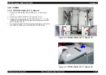
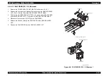
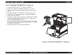
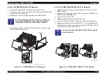
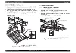
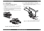
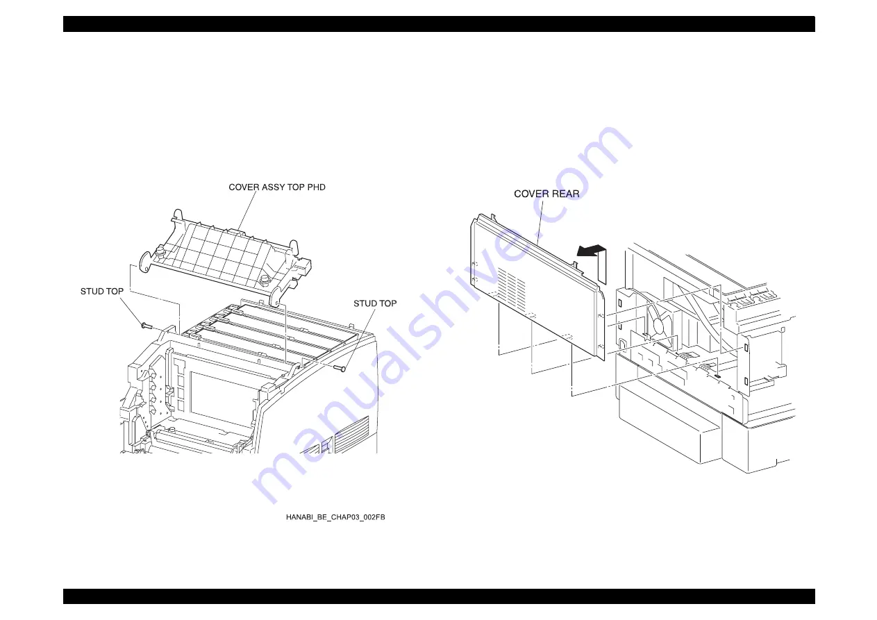
4.2.4.5 COVER ASSY TOP PHD (PL1.1.15) Removal
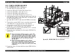
1. Remove the COVER ASSY TOP MAIN. (See Section 4.2.4.4.)
2. Remove the COVER SIDE L. (See Section 4.2.4.14.)
3. Open the COVER ASSY TOP PHD from the printer body.
4. Pull out the STUD TOP (PL1.1.29) securing the COVER ASSY TOP PHD
at the left and right.
5. Remove the COVER ASSY TOP PHD from the printer body.
Figure 4-10. COVER ASSY TOP PHD (PL1.1.15) Removal
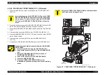
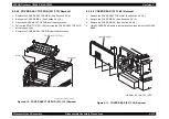
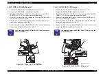
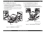
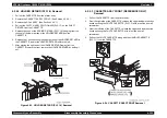
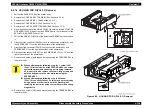
4.2.4.6 COVER REAR (PL1.1.28) Removal
1. Remove the COVER ASSY TOP MAIN. (See Section 4.2.4.4.)
2. Remove the COVER SIDE L. (See Section 4.2.4.14.)
3. Remove the COVER SIDE R. (See Section 4.2.4.9.)
4. Lift the COVER REAR a little in the rear direction, then remove the COVER
REAR.
Figure 4-11. COVER REAR (PL1.1.28) Removal
HANABI_BE_CHAP03_107FA
Summary of Contents for AcuLaser C3000 Series
Page 20: ...C H A P T E R 1 PRODUCTDESCRIPTIONS ...
Page 71: ...C H A P T E R 2 OPERATINGPRINCIPLES ...
Page 118: ...C H A P T E R 3 TROUBLESHOOTING ...
Page 318: ...C H A P T E R 4 DISASSEMBLYANDASSEMBLY ...
Page 472: ...C H A P T E R 5 ADJUSTMENT ...
Page 477: ...C H A P T E R 6 MAINTENANCE ...
Page 491: ...C H A P T E R 7 AcuLaserC4100 ...
Page 548: ......
Page 549: ......
Page 550: ......
Page 551: ......
Page 552: ......
Page 553: ......
Page 554: ......
Page 555: ...C H A P T E R 8 AcuLaserC3000 ...
Page 579: ...Model AcuLaser C3000 Board C569MAIN BOARD Sheet 1 of 5 Rev B ...
Page 580: ...Model AcuLaser C3000 Board C569MAIN BOARD Sheet 2 of 5 Rev B ...
Page 581: ...Model AcuLaser C3000 Board C569MAIN BOARD Sheet 3 of 5 Rev B ...
Page 582: ...Model AcuLaser C3000 Board C569MAIN BOARD Sheet 4 of 5 Rev B ...
Page 583: ...Model AcuLaser C3000 Board C569MAIN BOARD Sheet 5 of 5 Rev B ...
Page 584: ...C H A P T E R 9 APPENDIX ...
Page 674: ......
Page 675: ......
Page 676: ......
Page 677: ......
Page 678: ......
Page 679: ......
Page 680: ......


