EPSON AcuLaser C4000/C4100/C3000
Revision F
Disassembly and Assembly
Disassembly Assembly Procedures
4-413
4.2.19 CONTROLLER BOARD
4.2.19.1 PWB CONTROLLER (PL16.1.5) Removal
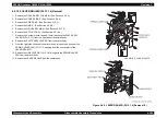
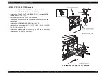
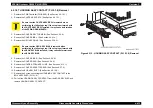
1. Loosen the 2 SCREW KNURLING (PL16.1.6) securing the PLATE REAR
ESS (PL16.1.7) at the back of the printer body.
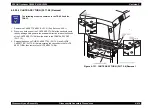
2. Hold the knobs of the GUIDE L ESS (PL16.2.12) and the GUIDE R ESS
(PL16.1.13), and remove the PWB CONTROLLER from the printer body.
3. When OPTION BOARDS are installed in the slots on the PWB
CONTROLLER, remove them.
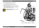
4. Remove the 1 screw securing the USB connector to the PLATE REAR
ESS.
5. Remove the 2 screws securing the parallel connector to the PLATE REAR
ESS.
6. Remove the 5 screws securing the PLATE REAR ESS to the BASE
PLATE.
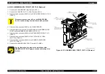
7. Remove the 2 screws (silver, 8mm) securing the rear of the PWB
Controller (PWB ESS) to the GUIDE L ESS, GUIDE R ESS (PL16.1.12),
(PL16.1.13).
8. Shift the PLATE REAR ESS to the rear to remove it.
9. Open the GUIDE L ESS and the GUIDE R ESS to the left and right, and
then remove it.
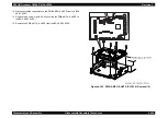
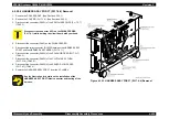
10. Remove the 12 screws securing the PWB Controller to the BASE PLATE.
11. Remove the 3 prop screws for HDD to the BASE PLATE, and then remove
the PWB Controller.
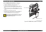
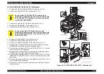
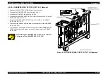
Figure 4-114. PWB Controller (PL16.1.5) Removal 1
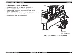
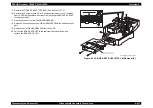
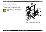
Figure 4-115. PWB Controller (PL16.1.5) Removal 2
C A U T I O N
When performing the following step, eliminate static
electricity from your body by using a grounding wristband
or other static eliminator. A discharge of static electricity
can damage the PWB CONTROLLER or the OPTION
BOARDS.
USB Connector
Parallel Connector
Step 6
Summary of Contents for AcuLaser C3000 Series
Page 20: ...C H A P T E R 1 PRODUCTDESCRIPTIONS ...
Page 71: ...C H A P T E R 2 OPERATINGPRINCIPLES ...
Page 118: ...C H A P T E R 3 TROUBLESHOOTING ...
Page 318: ...C H A P T E R 4 DISASSEMBLYANDASSEMBLY ...
Page 472: ...C H A P T E R 5 ADJUSTMENT ...
Page 477: ...C H A P T E R 6 MAINTENANCE ...
Page 491: ...C H A P T E R 7 AcuLaserC4100 ...
Page 548: ......
Page 549: ......
Page 550: ......
Page 551: ......
Page 552: ......
Page 553: ......
Page 554: ......
Page 555: ...C H A P T E R 8 AcuLaserC3000 ...
Page 579: ...Model AcuLaser C3000 Board C569MAIN BOARD Sheet 1 of 5 Rev B ...
Page 580: ...Model AcuLaser C3000 Board C569MAIN BOARD Sheet 2 of 5 Rev B ...
Page 581: ...Model AcuLaser C3000 Board C569MAIN BOARD Sheet 3 of 5 Rev B ...
Page 582: ...Model AcuLaser C3000 Board C569MAIN BOARD Sheet 4 of 5 Rev B ...
Page 583: ...Model AcuLaser C3000 Board C569MAIN BOARD Sheet 5 of 5 Rev B ...
Page 584: ...C H A P T E R 9 APPENDIX ...
Page 674: ......
Page 675: ......
Page 676: ......
Page 677: ......
Page 678: ......
Page 679: ......
Page 680: ......

