EPSON AcuLaser C4000/C4100/C3000
Revision F
Disassembly and Assembly
Disassembly Assembly Procedures
4-415
4.2.20 Large Capacity Paper Unit
(Option FEEDER UNIT)
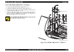
4.2.20.1 COVER FRONT (PL17.1.5) Removal
1. Remove CASSETTE TRAY 2 and 3, and any others of the type that can be
withdrawn, by pulling them straight out then tilting them up to take them all
the way out.
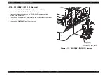
2. Release the 3 hooks securing the COVER FRONT to the FRAME ASSY
OPF (PL17.1.3), and remove the COVER FRONT.
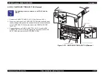
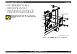
Figure 4-117. COVER FRONT (PL17.1.5) Removal (1)
C A U T I O N
When removing the lower COVER FRONT, release the 3
hooks with a tool like a screwdriver.
When putting the cover back on, be careful of which side is
the top and which is the bottom. Also, be sure to align the
slot of the COVER FRONT (PL17.1.5) with the opening of the
FRAME ASSY OPF.
Summary of Contents for AcuLaser C3000 Series
Page 20: ...C H A P T E R 1 PRODUCTDESCRIPTIONS ...
Page 71: ...C H A P T E R 2 OPERATINGPRINCIPLES ...
Page 118: ...C H A P T E R 3 TROUBLESHOOTING ...
Page 318: ...C H A P T E R 4 DISASSEMBLYANDASSEMBLY ...
Page 472: ...C H A P T E R 5 ADJUSTMENT ...
Page 477: ...C H A P T E R 6 MAINTENANCE ...
Page 491: ...C H A P T E R 7 AcuLaserC4100 ...
Page 548: ......
Page 549: ......
Page 550: ......
Page 551: ......
Page 552: ......
Page 553: ......
Page 554: ......
Page 555: ...C H A P T E R 8 AcuLaserC3000 ...
Page 579: ...Model AcuLaser C3000 Board C569MAIN BOARD Sheet 1 of 5 Rev B ...
Page 580: ...Model AcuLaser C3000 Board C569MAIN BOARD Sheet 2 of 5 Rev B ...
Page 581: ...Model AcuLaser C3000 Board C569MAIN BOARD Sheet 3 of 5 Rev B ...
Page 582: ...Model AcuLaser C3000 Board C569MAIN BOARD Sheet 4 of 5 Rev B ...
Page 583: ...Model AcuLaser C3000 Board C569MAIN BOARD Sheet 5 of 5 Rev B ...
Page 584: ...C H A P T E R 9 APPENDIX ...
Page 674: ......
Page 675: ......
Page 676: ......
Page 677: ......
Page 678: ......
Page 679: ......
Page 680: ......


